GC_ET.html


2022-08-29   01:13:35

   ( Be sure to Refresh your pages, each visit,   { F5 } 
  ( web-site construction has been ongoing since 1994, for 27 years  


---    all about  Analog Active Filters
          and  Electronic_Technology 
  
                        and
   Ham Radio
circuits
            for Receiving
  Morse-Code    

    Original Radical Analog Designs  for  'CW' filtering circuits                             

     aimg_Morse-Man    *****************  Ham K4KKQ running CW for 63 years **************************************************    FISTS_animated_logo-444.gif

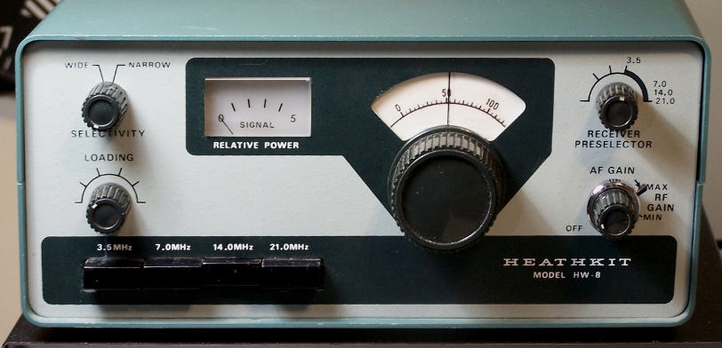
*********************       HW8-portrait       KNWD-830-portrait.jpg       

__________________________________________________________________________________________________________________

Be sure to read the page on    < Radical All-Pass Projects >   

Non-Linear Non-Resonant   AllPass_Experimental_Filters  Dual-Notch  Phase-Filter   Projects 


********(  Home  )********************************************************************************


>>   AFX Advanced Filter    ( read AFX basic FIRST )

>>   AFX Roof-Triad Filter    ( read AFX basic FIRST ) 


>> AFX 'V'_  _Variable f() Filter        ( read AFX basic FIRST )   ( AFX 'V' is the Best-of-Class project )

!!!  Advanced Variable Frequency version of the  'AFX' project     

( AFX 'V' is the Best-of-Class project )

>> AFX 'V'__Variable f() Filter    ( read AFX basic FIRST )   ( AFX 'V' is the Best-of-Class project )

>> Summary List for AFX 'V' : 
(1RL-Manual Control)    (3RL-Manual Control)      (1RL-Fet Control)   (3RL-Fet Control)    


********************************************************************************* 
 

>> AFX Basic Filter    is the current page --- please read through this page first ! 

>>    then read the sub-pages for greater basic details. 

*********************************************************************************
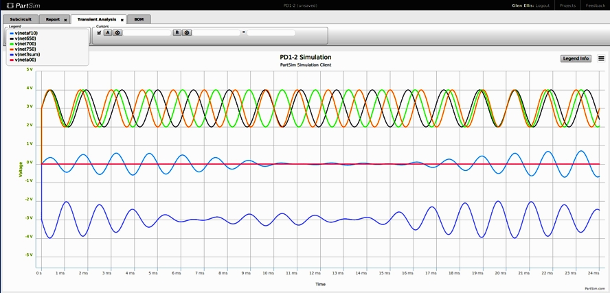
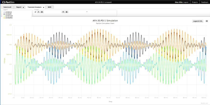
Below:  Transient Plot shows Phase Delays and inter-actions. 
Triple-Signals are phase-shifting across time. (600Hz , 700Hz , 800Hz ) 
Note: Filter (top trace ) forces phase shifting on input signal and produces a symetrical output signal
.
Note: Filter (blue trace) responds to the beat frequencies with peaks and nulls in its output.

                PD1-2-TS-24ms-150803-0800.jpg
 

/glene77is/GC_ET_files/PD1-2-TS-24ms-150803-0800.jpg

**********************************************************************************


PreRequisite : 

This is not an academic Algebra / Calculus based tutorial. 
It is expected that the reader will have a good understanding
of Active BandPass Filter Concepts. 


This website & project does not contain an in-depth presentation
of basic Delyanis Multi-Feed-Back Filter , nor derivatives.

All concepts presented herein are common to Active BandPass Filters
as presented in tutorials and academic course-work
presented for Electrical Engineering students.

ONLY the SYNTHESIS of common ideas into radically new approaches is different. 

Your Imagination is more important than prior academic learning. 
 

About this project :  

This project is our Current research in Analog I.C. Applications,
     2014 thru 2021,
as applied to CW (morse code) Radio Operations
... posted at www.GeoCities.WS/glene77is   
... posted at www.ResearchGate.net


Our Analog Project shows the evolution of filter design
from common Active BandPass circuits into Active Phased-Filtered circuits. 

  
() This project has produced a Series of Analog Filters aproaching DSP quality    
()      which Emphasize   Original Radical Designs .
()      which Emphasize   Phased-Filters and Parallel-Channel-Filters to generate Dual-Notch effects.
() This experimental project
()        is about Analog Electronic Technology applied to Amateur Radio operations.   
()        is applied to Narrow Band-Pass Morse Code CW operations.

Our project's Applications could also include in-lab analog instrument filters
where the circuit is proto-boarded and no PC/computer required .

****************************************************************************************************
Basic AFX circuit includes these modules:

1.  Pre-Amp with Limiter
2.  Roofing Parallel-Channel-Differential Filter 
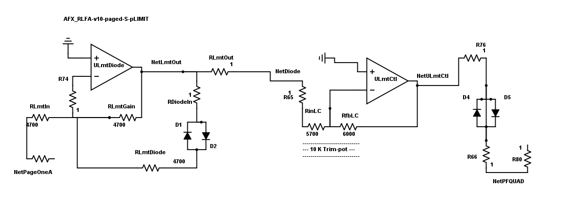
3.  Active-Log_limiter 
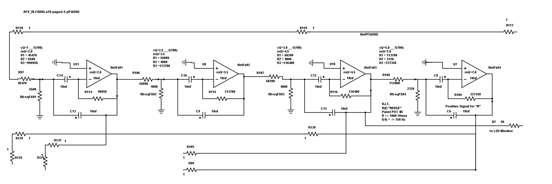
4.  Quad-MFB audio filter 
5.  Differential-Phase Filter with Double-Notched Band-Passband.
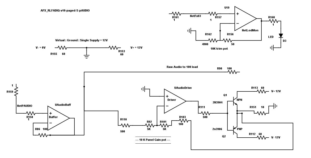
6.  Audio out 0.5 W class-B 


***********************************************************************************


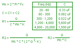
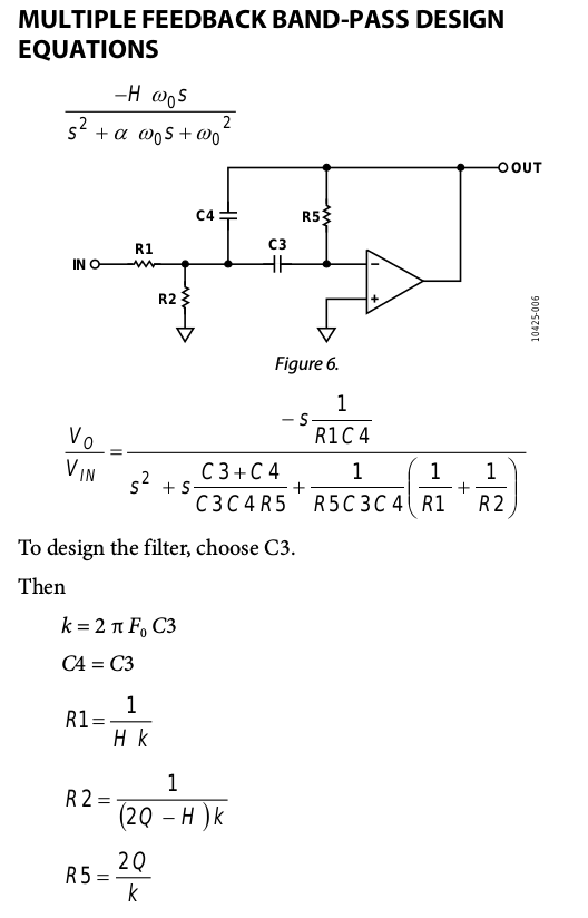
AFX_equation_Band-Pass-Function_.png   ET_BandPassFilter_MFB_K7MEM_equ.gif   MFB_BPF_equations_TI_.pngCW_K-quality-example_simplot-fourier-series-2.png


******************************************************************************************

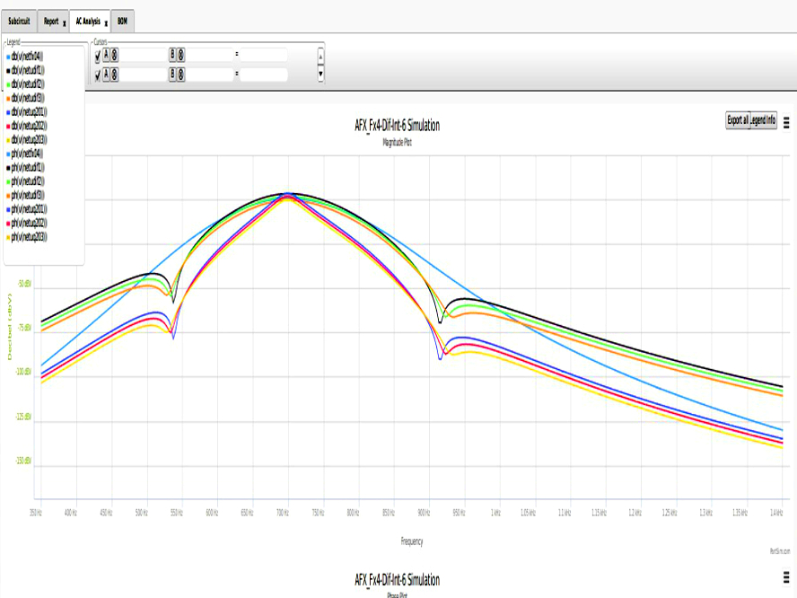
******       The AFX 'basic' designs include these features :
******       BandPass 90Hz @ -3dB and 340Hz @ -60dB, 
******       SideBand Spread =  5Hz per dB attenuation
******       Dual-Notch BandPass = -90 dB  @  350Hz bandpass  
*******      Variable-Frequency  PassBand  (600-700-800)
           AFX_Fx4-Dif-Int-pFXTRA-6-M-160827-0800-sq.jpg      

AFX_RLFA-v9-paged-1-B-all-ani-00.gif 


*********************************************************************************************************************
 

Below are the Functional Blocks of the General AFX circuit development


*******************************************************************************************************


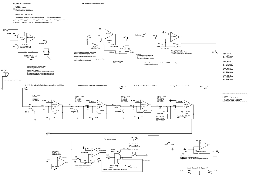
   the   "AFX"  B.A.S.I.C.  Simple  Schematic  (basic)  

( goto Schematics Page for Hi-res )

                             where it all started simply 
 
AFX_BASIC-v1-7-S.png  

*************************************************************************************************************************************

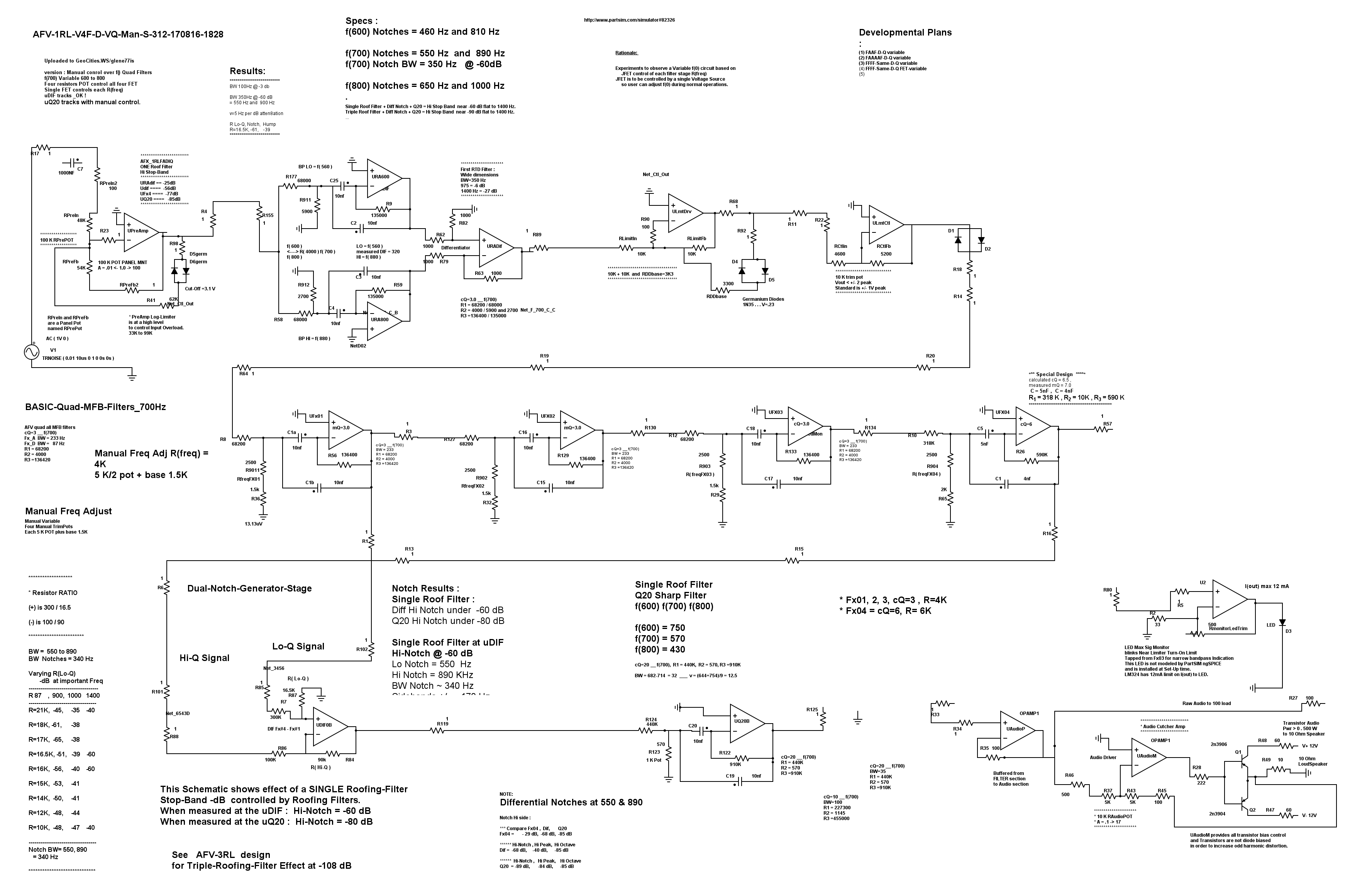
   the  "AFX" Advanced  Schematic  ( Phase-Filtered Dual-Notch version) 
       ( goto Schematics Page for hi-res )

  AFV-1RL-V4F-D-VQ-Man-S.png

*************************************************************************************

Revised details and hi-res schematics are in the section "AFX" 'V'  
for the Phase-Filtered Dual-Notch Filter developments 

*************************************************************************************


******************************************************************************************************

*** Below : the TUTORIAL Pages : 

*** This Page is an Index into the  Modular Stages that Build the AFX 

******* below : each of the linked pages contain detailed discussion and schematics and bode plots
******* below : each of the linked modular circuits are included in the advanced "AFX" projects. 


aimg-radio-button.png
_____________the   AFX  Roofing-Triad-Differential  Filter details
  (GC_ET_AFX_CW_Roof.html)           


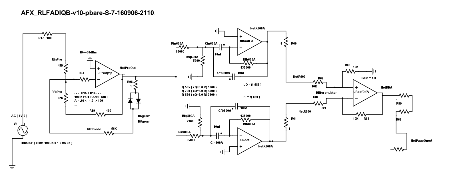
AFX_RLFADIQB-v10-pROOF-S.png


___________________________________________________________________________________________________________________________________________________________________________________________

aimg-radio-button.png  

  _______ the   AFX  Active-Log-Limiter stage details :    (GC_ET_AFX_CW_Limiter.html)
      AFX_RLFADIQB-v10-pLIMITER-S.png


____________________________________________________________________________________________________________________________________________________________________

aimg-radio-button.png                        


______________the  AFX  Quad-MFB Filter details    (GC_ET_AFX_CW_Filter.htm) 
 

AFX_RLFADIQB-v10-pFQUAD-S.png


_____________________________________________________________________________________________________________________________________________________________

aimg-radio-button.png

Differential-Phase-Filter
& Integrating-Phase Filter 
& Q20 Sharp Variable f(0) filter


  AFX  
Phase-Filter Circuit_ 

        (GC_ET_AFX_CW_FiltDIQ.html)


   When Combined with Roof-Triad-Differential-Filters,
    and the Quad-MFB-Band-Pass Filters, 
    the "A" stage Phase-Filter can produce  Dual-Notches at -98 dB 
    Variance = 7 Hz sideband spread per dB attenuation 

Refer to the above link for the details of the Phase-Flter stages. 

"A" narrow Notch stage on left.    "B" Wide stage center.   "C" Q20 Sharp Band-Pass Follower Filter. 

AFX_RLFADIQB-v10-pFXTRA-S.png


_____________________________________________________________________________________________________________________________________________________________________________________________________________________

_________    AFX Audio Driver  with Pulse-Signal-Shaping  (GC_ET_AFX_CW_Audio.html) 
AFX_RLFADIQB-v10-pAUDIO-S.png


***************************************************************************************************************
Above are the Functional Blocks of the General AFX circuit development


***************************************************************************************************************


**************************************************************************
aimg-PhaseD.jpgCW_K-quality-example_simplot-fourier-series-2.png

-------------------------------------------------------------------------------------------------------- 

*** ET_Fliege_Filter 

*** ET_Analog_SideBand_Filter

*** ET_Filter-Incremental-Tuning


***   GC_ET-OPA-AC.html     OpAmp with Active Phase Compensation


*** CALF_a-Fine-Club-Project-Kit-by-KC9on


*** ET_State-Variable_Filter


*** ET_Antoniou_Filter (" the Gyrator Filter")
 

*** Phased-Signal Analysis :  

**************************************************************************


*** Early Parallel-Dual-Channel Developmental circuits 

*** Notched-Filter_7N

*** Notched-Filter_AAN

***    PC2D : Parallel  Dual-Channel + Differential   CW Audio Filter Page. 

***     P2S : Parallel-to-SumPFB-osc
***     P2D : Parallel-to-Differential
 

************************************************************************************

  ( Josef Punčochář
Associate Professor  
VŠB-Technical University of Ostrava,    · Department of Electrical Engineering 
_______Original Design for Positive-FeedBack BandPass Filter.   ( GC_ET_PFB-rg.html )
___Positive-FeedBack_BandPass_Filter   ( GC_ET_PFB-rg.html )

___Positive-FeedBack_Sine_Oscillator, with one resistor f(0) control_and magnitude_control.
 

***  Positive-FeedBack-BandPass_Circuits 

  GC_ET_PFB-bpf.html    Positive FeedBack BandPass Filter 

GC_ET_PFB-osc.html  Positive FeedBack Osc


*********************************************************************************************


       Articles of Interest relating to CW Audio Filtering        Q-n-BW-resonant-plot.png
 

   ( NeScaf )


   ( HiPerMite )


********************************************************************************************************** 

   ( Author's BreadBoard )
   ( Notes from University of Tennessee, 1977 - 1997 ) 


******** (  Home ) ********************************************************************************************************************************

   aimg_Morse-Man

****(   home )************************************************************