GC_ET_AFX_P2S.html
2021-01-06 11:08:48
 (Home) the "P2S" page
**********************************************************************************
"Par2SumQ" radically different Dual-Channel CW Audio Filters
**************************************************************************************************
The designed advantages coming from the P2S approach are :
1) a flat-topped Passband, for easier capture of CW signals.
2) steeper sideband skirts, ( one circuit at 12 stages approachs Brick-Wall measurements).
The disadvantage is greater complexity in tuning the many dual channel stages.
******************************************************************************************************
Note: In the following diagrams, R2 to Virtual Ground is the R(freq) for adjusting f(center)
Note: the -3dB level is equivalent to the 700 mV level in these Bode Plots.
*******************************************************************************************************
*****************************************************************************************
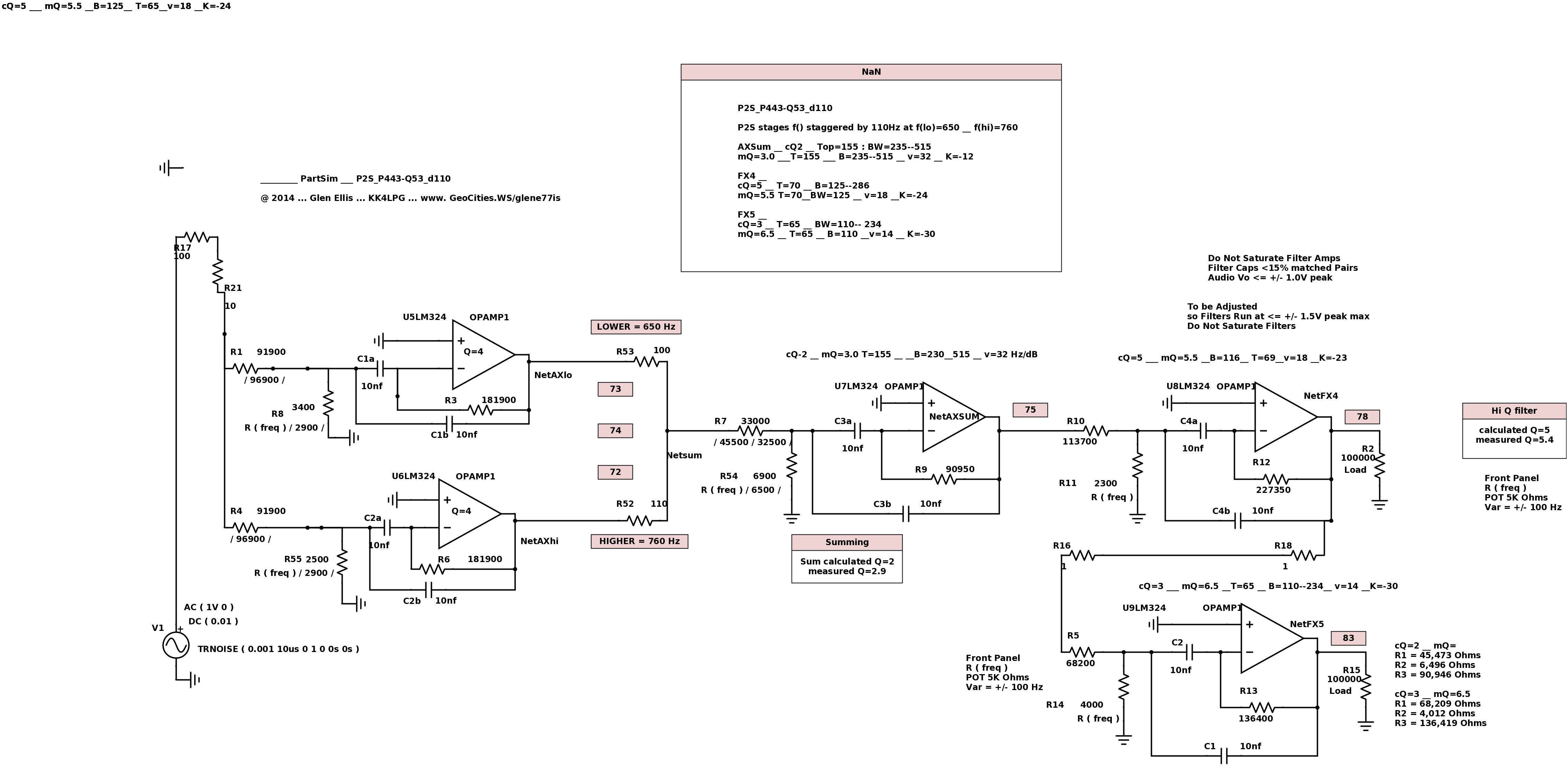
"P2S" Triplet Filter plus two "Q" stages labeled "P2S-P442-Q53"
This "P2S" circuit is applied as a Narrow CW Filter in Four/Five stages,
using MultiFeedBack circuits and a Butterworth curve. Good and Simple design.
Filter, selectable "W"ide (BW=235) and "N"arrow (BW= 110 Hz)
SideBand skirts are very steep.
Dual Channels are 110 Hz apart.
This circuit works good for a 5 stage filter.
Results depend on exact amount of Dual-Channel Spread and number of "Q" Stages.
Last Stage Filter:
measured "Q" = 6.5 __max
Top = 65Hz __ at -1dB
BW = 110 __ at -3dB
Variance = 14 Hz per dB attenuation __
*********************************************************************
This "P2S" circuit is applied as a Narrow CW Filter in a SIX stages,
using MultiFeedBack circuits and a Butterworth curve.
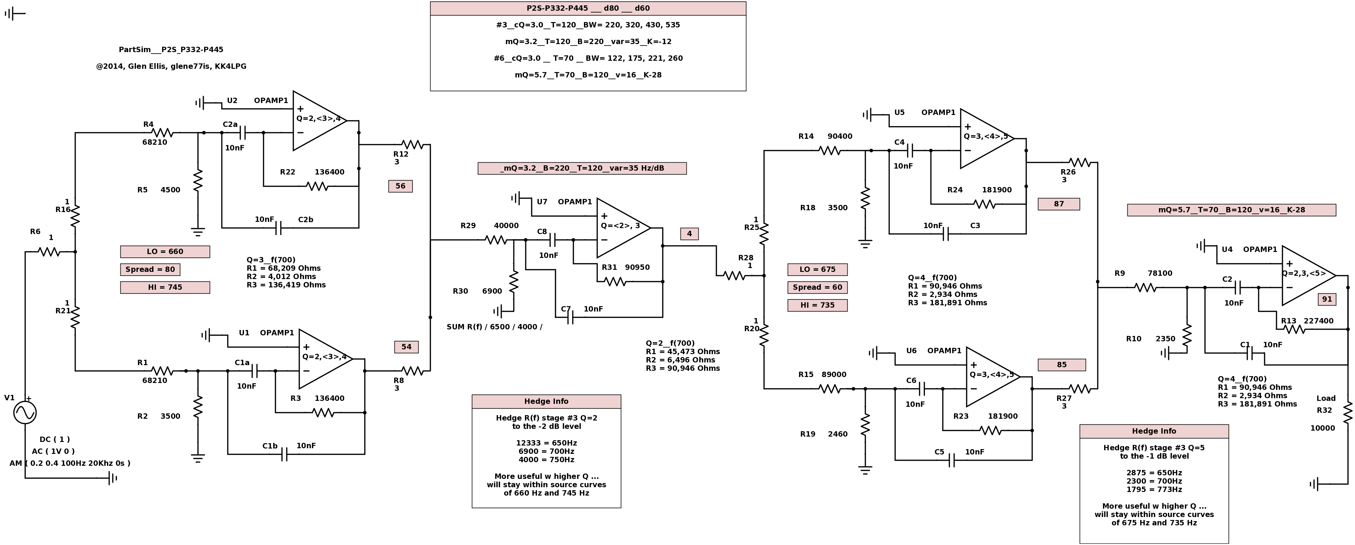
This P2S-P332-P445 design uses two sets of Triplet Filters.
Results depend on specfic amount of Dual-Channel Spread and "Q".
Wide
mQ=3.0__T=120__BW=220__var=35__K=-12
Narrow
mQ=5.7__T=70__BW=120__var=16__K=-28
measured "Q" = 5.7 __ Top = 70Hz __ BW = 120 __ Variance = 16 Hz per dB attenuation __ Kilo = -28dB at 1000 Hz
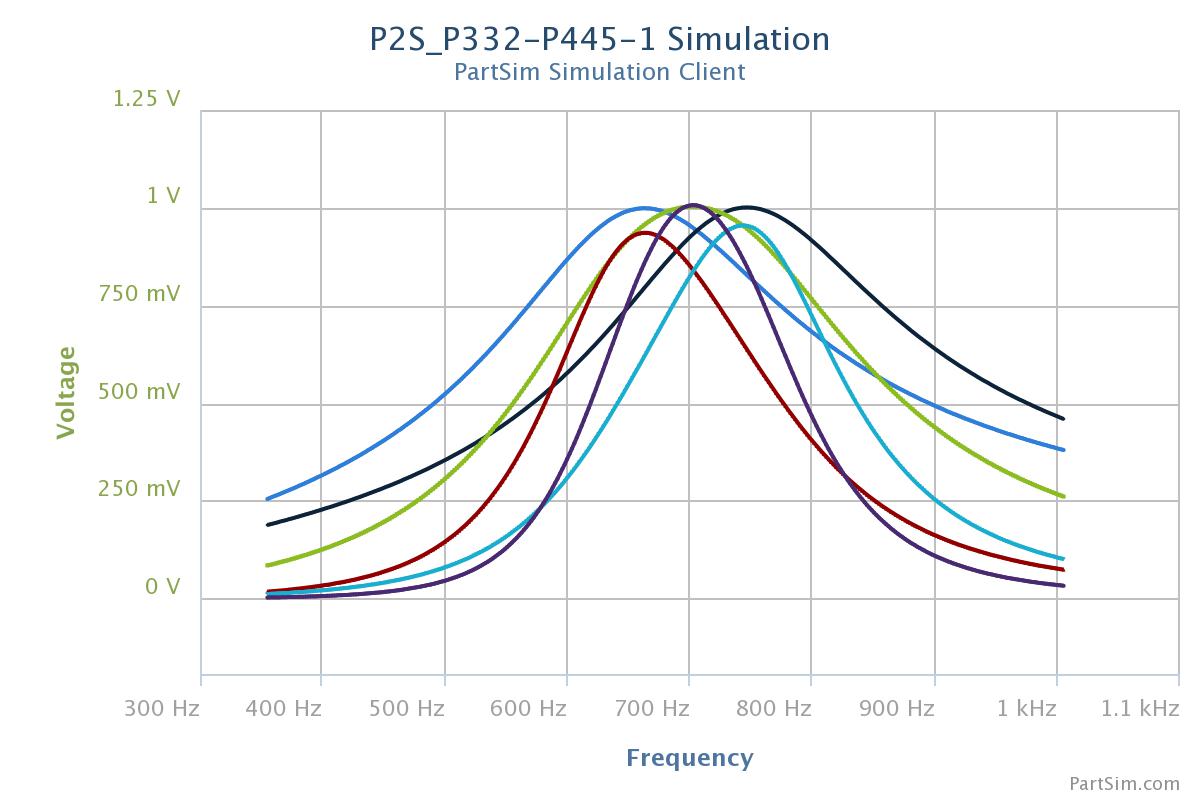
In each of the Triplet Groups, the OpAmp filters #1 and #2 are staggered (hi / lo of each other)
and #3 is a Summing stage with a Low "Q".
Staggers here are +/- 45Hz for First Triplet, and then +/- 30Hz for Second Triplet.
The result is a Flat-Top Bode plot, and steeper than normal SideBand Skirts.
This is labeled a "P2S-P332-P445" circuit,
where the P2S triplet filter "Q" = 3, 3, 2, and "Q"=4, 4, 5" .
Resulting Final Top BW at -1 dB is 70 Hz (Flat).
Resulting Final BandWidths are 120, 195, 240, 285 at the -3dB, -6dB, -9dB, -12dB levels.
Resulting Final Variance of BandWidth is 16 Hz per dB attenuation (Extremely Steep).
Resulting signal level of K = -28 dB at 1000 Hz.
Results depend on amount of Dual-Channel Spread. No precision components required.
Caps are +/- 5%, f() is corrected by the MFB circuit at R(freq) for each stage.
The P2SQ Triplet Filter #1 is caculated as Q=3,3,2, and measured as Q= 3.0, 3.0, 4.0 ,
due to the cumulative effect of sequental stages.
The P2SQ Triplet Filter #2 is caculated as Q=4,4,5, and measured as Q= 4.0, 4.0, 6.0 ,
due to the cumulative effect of sequental stages.
Stage #1 & #2: R(freq) is R5 and R2 for the base parallel filters.
Stage #3: R(freq) is R30, for the Summing "W"ide filter.
Stage #4 & #5: R(freq) is R18 and R19 for the base parallel filters.
Stage #6: R(freq) is R10, for the Summing "W"ide filter.
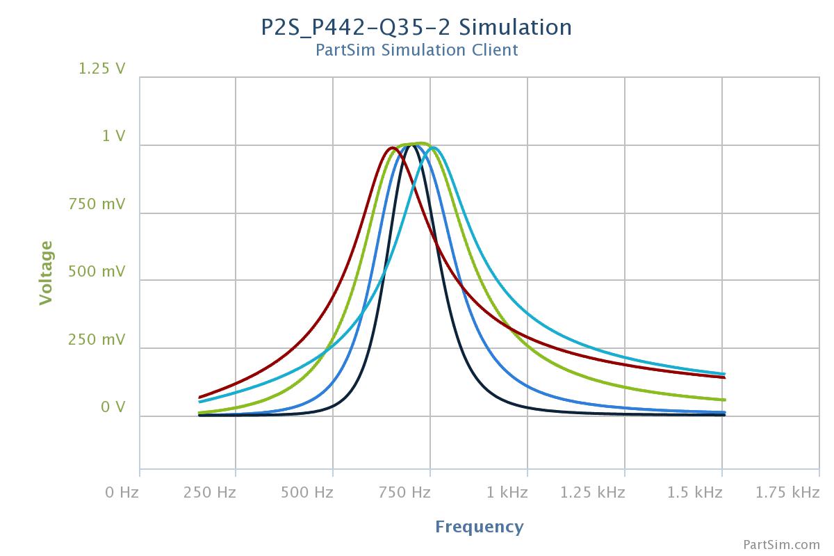
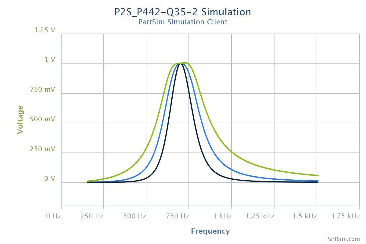
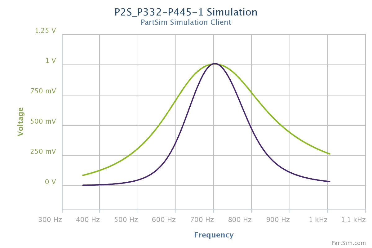
Below, note the "Green" and "Black" traces are the sums of the two staggered curve sets.
Very Flat Topped and Extremely Steep SideBand Skirts.
Narrow final stage has SideBand Skirts expanding at 16Hz per dB attenuation.
Nearly Straight Down. Here it is the BLACK trace.


************************************************************************************
************************************************************************************
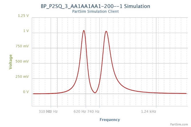
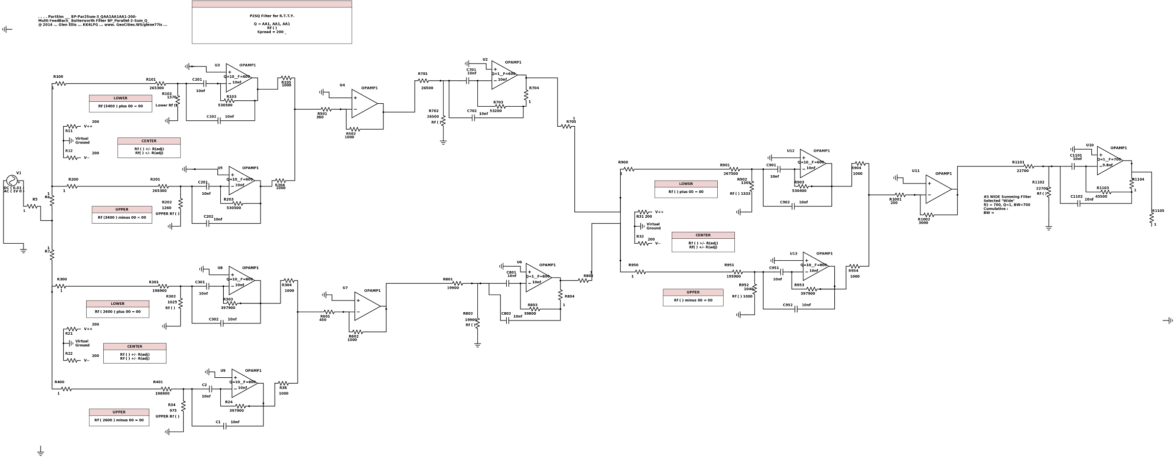
This "P2SQ" is applied as an Audio R.T.T.Y. Filter, at 600 Hz & 800 Hz.
The RTTY Twin-Peak has been phase inverted
and acts as a Twin-Notch around the narrow C.W. filter. ( see below )
*** Cumulative Filter Bode for RTTY Filter, P2S-3-AA1A1AA1 all phases showing :
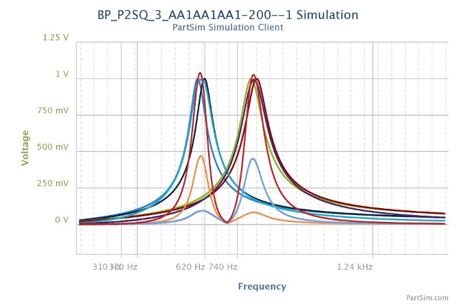
*** RED trace shows -48 dB Notch between RTTY peaks :
*** Schematic of P2S-PAA1AA1AA1 RTTY audio filter ( 12 filter stages )
*********************************************************************************************
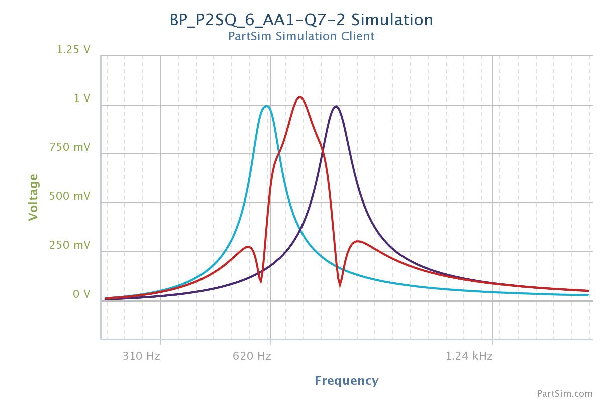
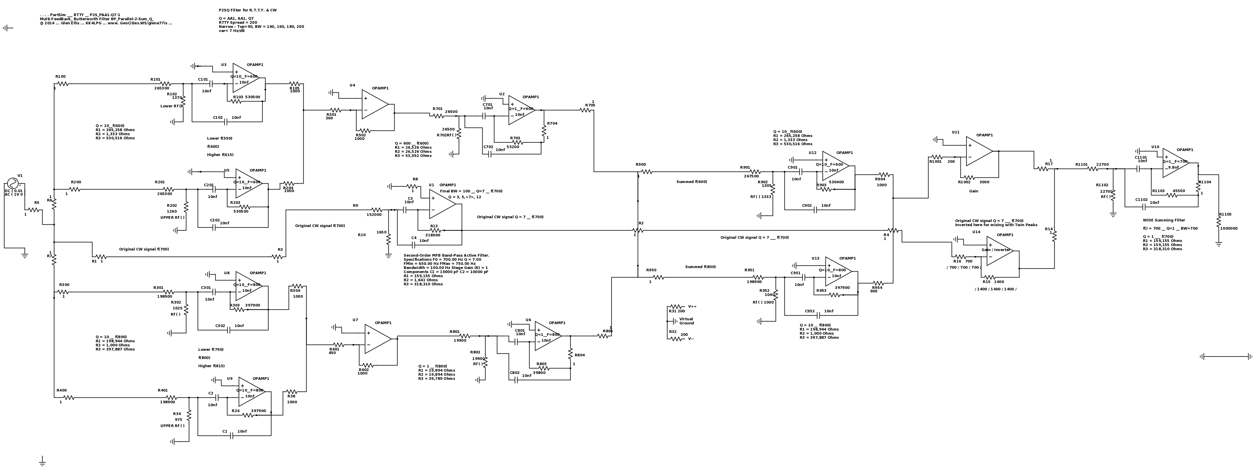
P2S-PAA1-Q7 is an Audio C.W. Filter, Final Q=7, at 700 Hz,
Design goal was to broaden the Top of the BandPass at the -3dB level ( here .700 mV)
and Steepen the SideBand Skirts between -3dB and -30 dB.
Here, the Twin-Peak signal is phase inverted
and acts as a Twin-Notch when summed around the narrow C.W. signal.
This Q=7 BandPass is about 100 Hz wide at -3dB,
and extremely steep skirts, spreading at 7 Hz per dB attenuation down to -30dB.
************************************************************************
************************************************************************
************************************************************************
Schematic ( 18 stages )
Design goal was to broaden the Top of the BandPass, and Steepen the SideBand Skirts.
Documentation embedded : P2S-PAA1-P445
This filter circuit has aprox. BW=90 and Sidebands Extremely Steep,
The sideband steepness has a rating a v=5 rating, K=-27
and will sound like a brick wall to signals outside of BP=120Hz.
This is NOT a club kit project.
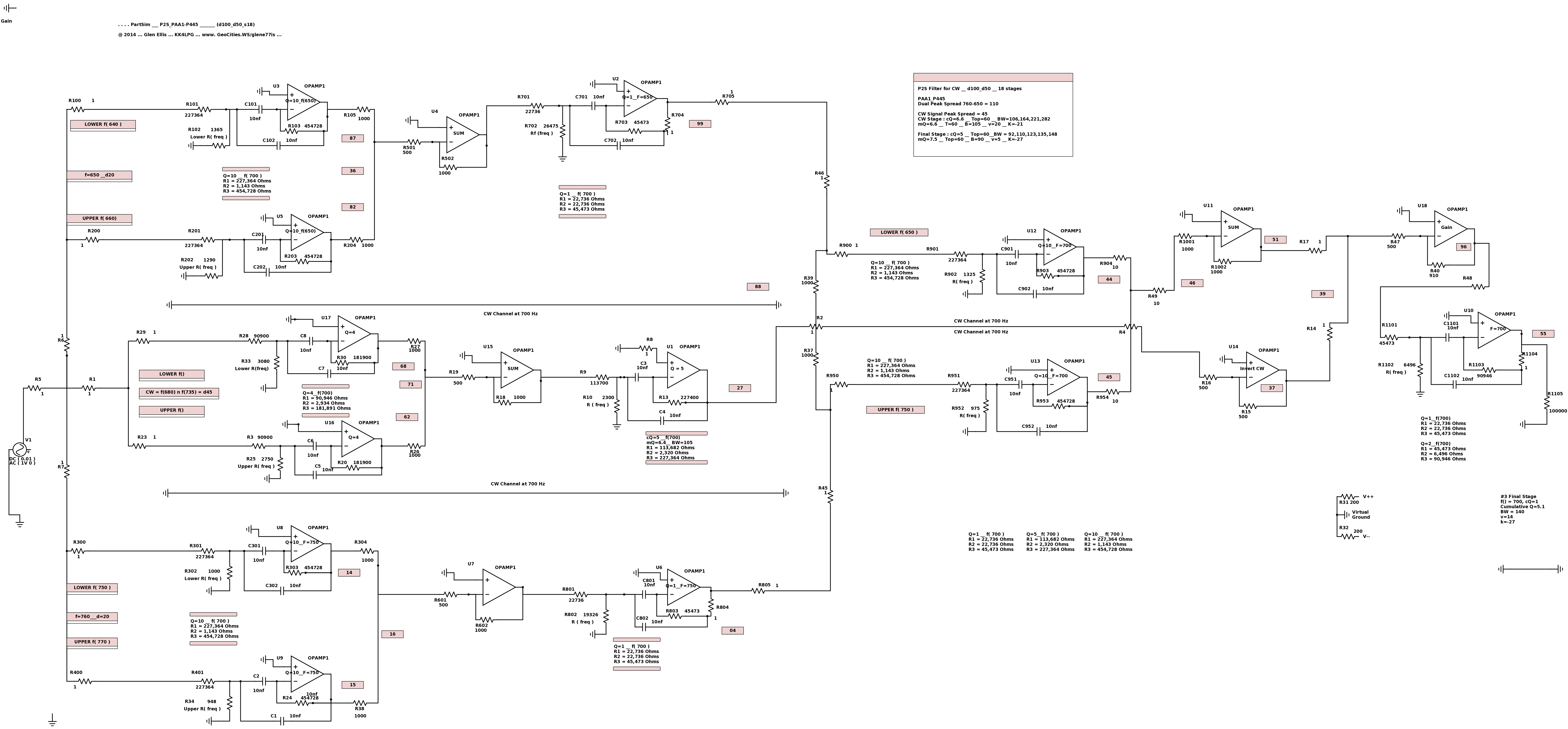
Not a Club Kit Project ! Tuning is critical and analog interaction is always present.
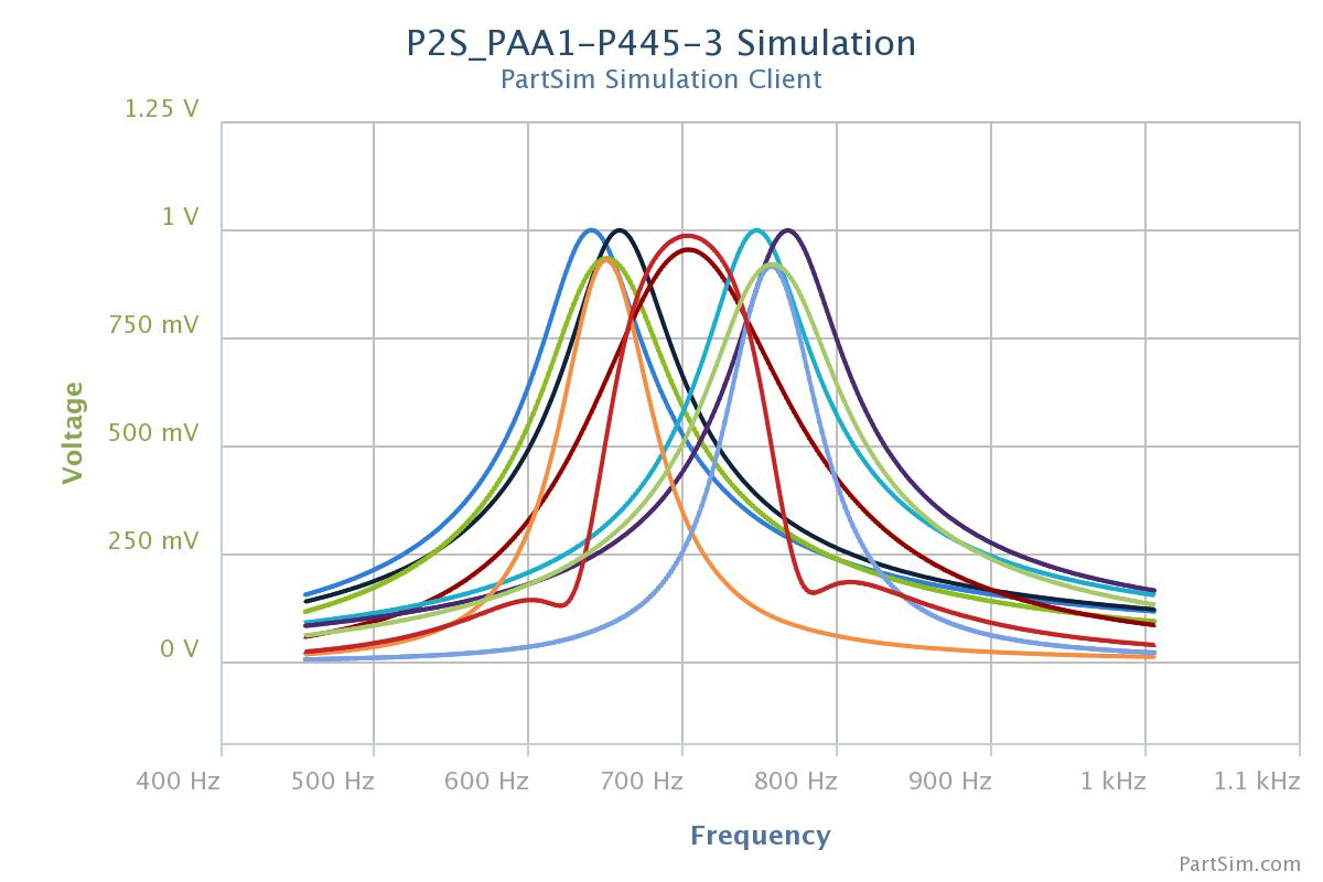
Here, the Dark-Red trace is the broader original CW signal
and the Light-Red trace is the narrow Double-Notched PassBand Signal.
****************************************************************************************
Revising This Section
*****************************************************************************************************************
 (Home) the "P2S" page
 (Home) the "P2S" page


