 Analog Roof-Triad-Differential Filter
 ************* Dual Channels and Differentiated Final Signal Output
GC_ET_AFX_CW_Roof.html
2021-01-06 09:27:37
 Analog Roof-Triad-Differential Filter
************* Dual Channels and Differentiated Final Signal Output
******** The AFX Analog ONE Roof-Triad-Differential_Filter *************
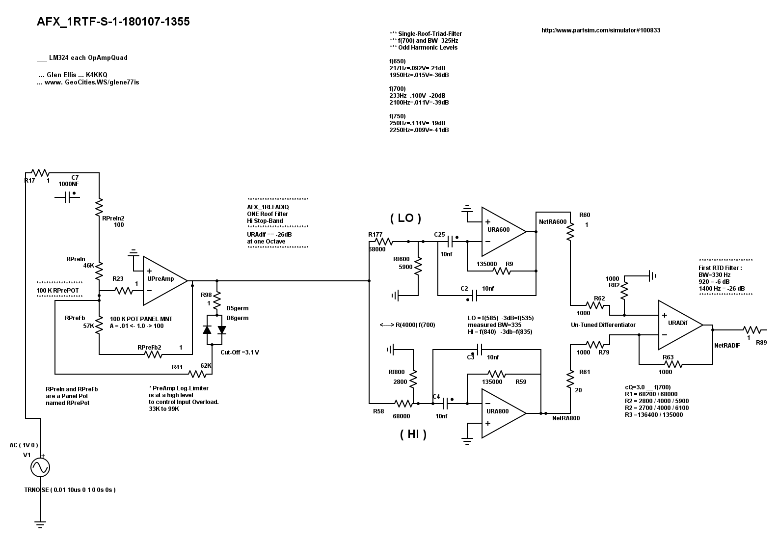
First , the preliminary stage is basically gain control with limiter.
The Lower Filter is tuned to 600 Hz. See schematic.
The Higher Filter is tuned to 800 Hz. See schematic.
These two different signals are Subtracted by the Differential Amp.
(1) This Roofing Filter circuit produces a flat-topped ( 330 Hz @ -3dB ) signal
with sideband attenuation of -27 dB per Octave .
(2) The Roofing Signal out has symetrical waveform.
This reduces intermodulation distortion within the following Active Limiter module.
*** section # ONE : Single Roof Triad Filter
*** Roofing Filter BW=300Hz, with Wide, Flat Top.
*** Sideband FallOff is -27 dB per octave; ie, 700 Hz = 0 dB and 1400 Hz = -27 dB.
*** "v"=32 Hz expansion per dB attenuation.
Note: All Filter and Differential stages are set to aprox. standard 1V peak
(a) to be above noise
(b) for easy visual analysis
Note: Power Supply ByPass caps are not shown.
OpAmp Null trim pots were not used, in this development with LM-324 quad OpAmp chips.
All Filter Stages are MFB, effectively AC audio coupled, thus self-centering.
Note: For each Roofing-Triad-Differential Filter :
On each Differential chip, the (+) 1K to ground should be adjusted
between 1K and
*******************************************************************************************************
*** Simply run this Single Roof-Triplet-Filter circuit before any standard CW audio filter circuitry.
*** The Single Roof-Triad-Differential filter can be sequenced easily for greater effect.
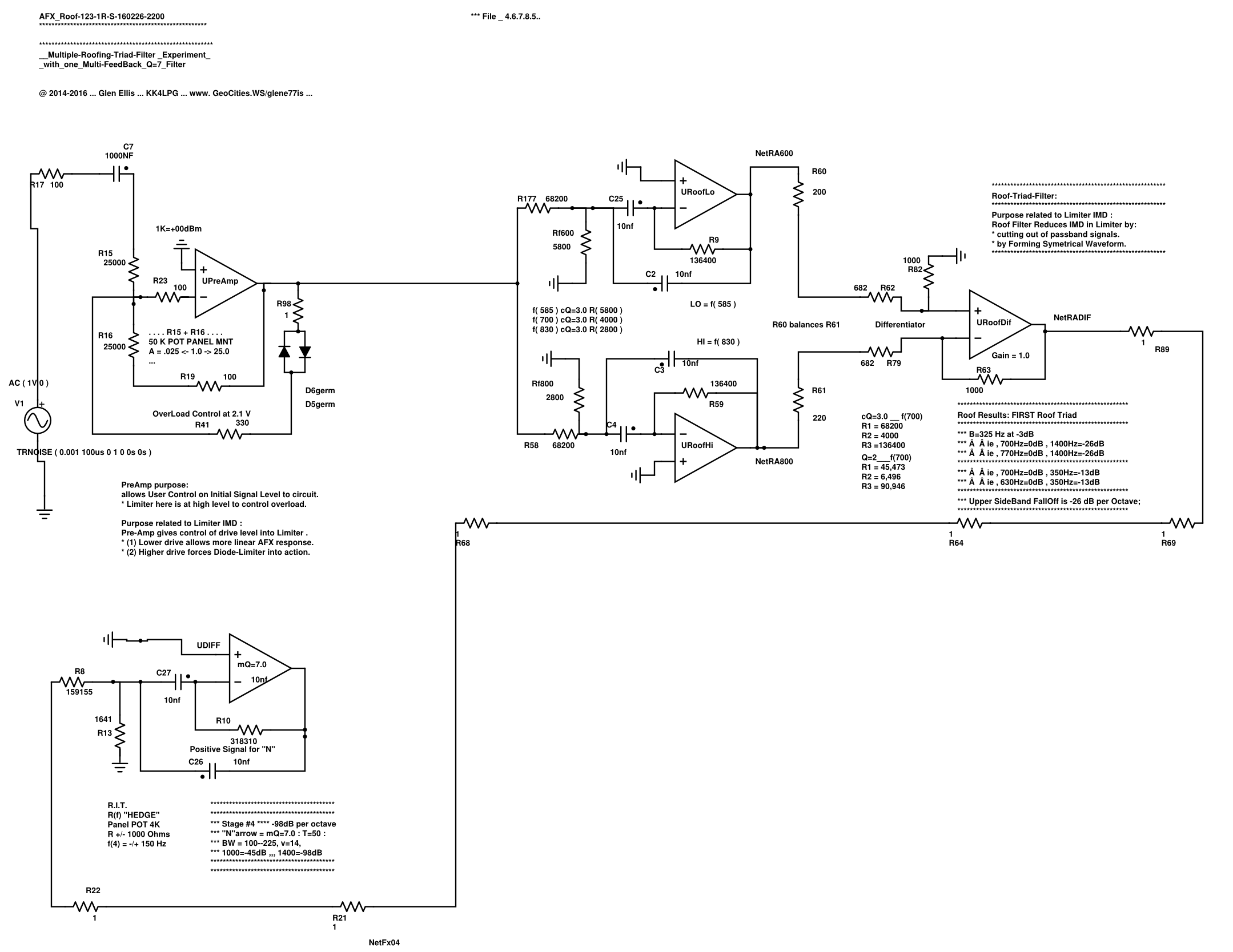
*** Below : the Single-Roof-Triad-Filter
*** with Parallel Initial Filtering and then followed with a DIFFERENTIAL final stage,
*** are the basic Roof-Triad-Differential Filter, as used in the "AFX" circuit.
***
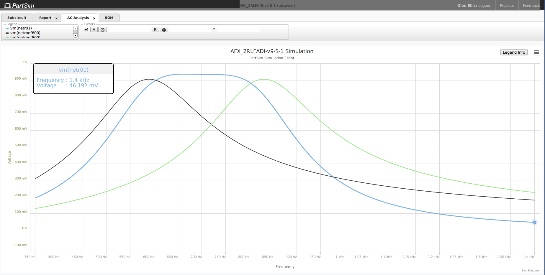
Single-Roof-Triad-Filter Function :
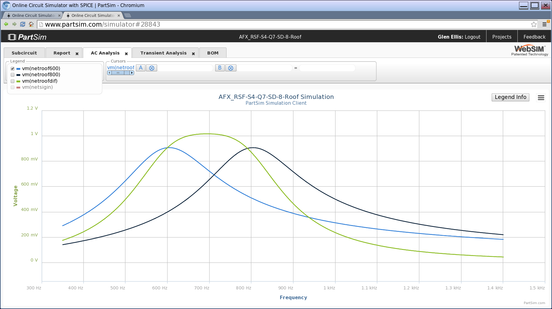
Frequency Domain "Bode" .
*** Sideband FallOff is -27 dB per octave ( blue trace )
*** Below :
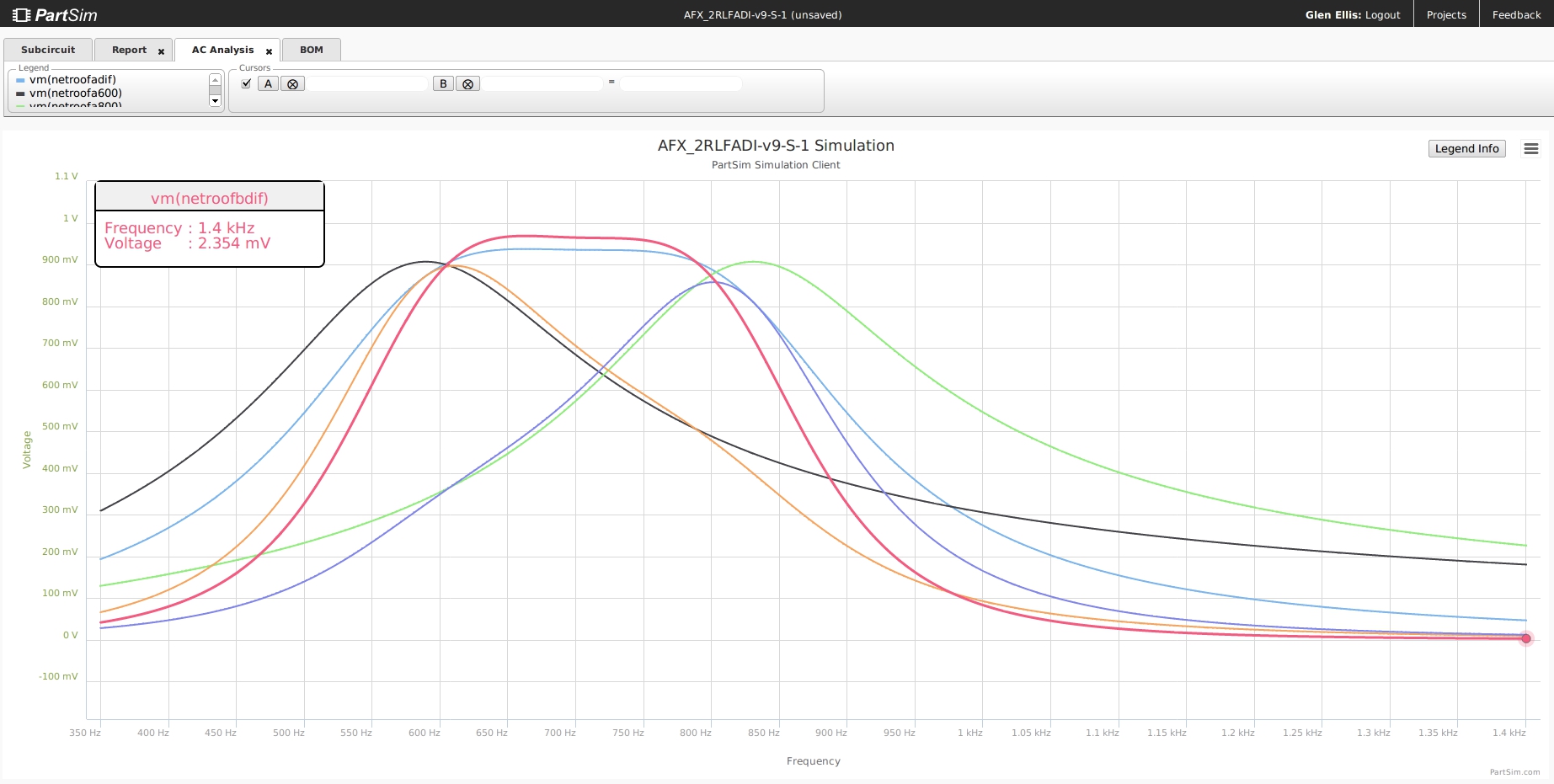
*** The Double Roof-Triad-Differential_Filter *******************
*** Vsignal=TR(noise) from ngSPICE and f(center)=700Hz
*** Differentiated Signal is about 250Hz wide at -3dB
*** Sideband FallOff is -54 dB per octave
*** ie, 700 Hz = 0 dB and 1400 Hz = -54 dB
*** Stop-Band = -60 dB to the limits
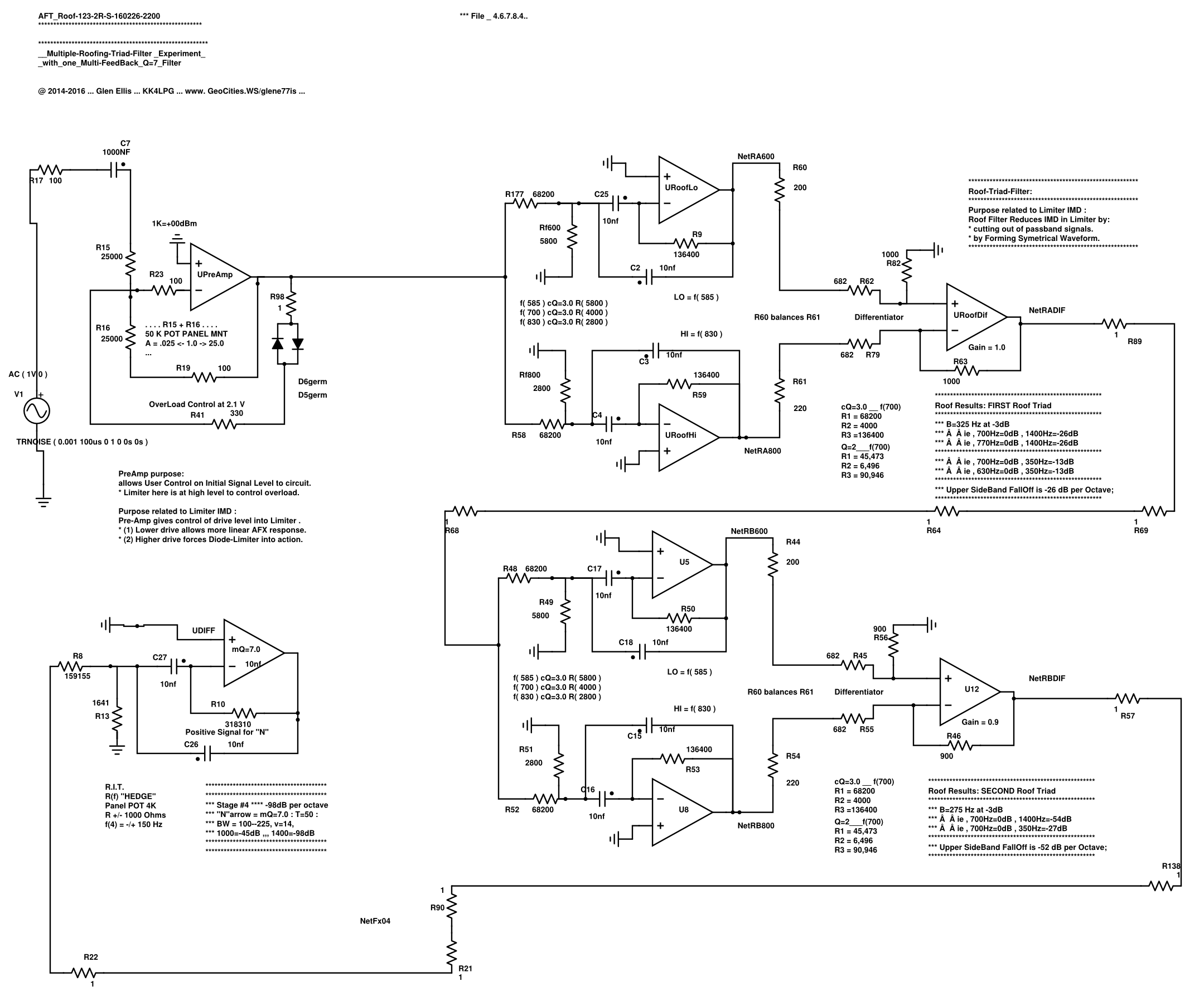
*** Sideband FallOff is -54 dB per octave ( red trace ).
***************************************************************
*** Below :
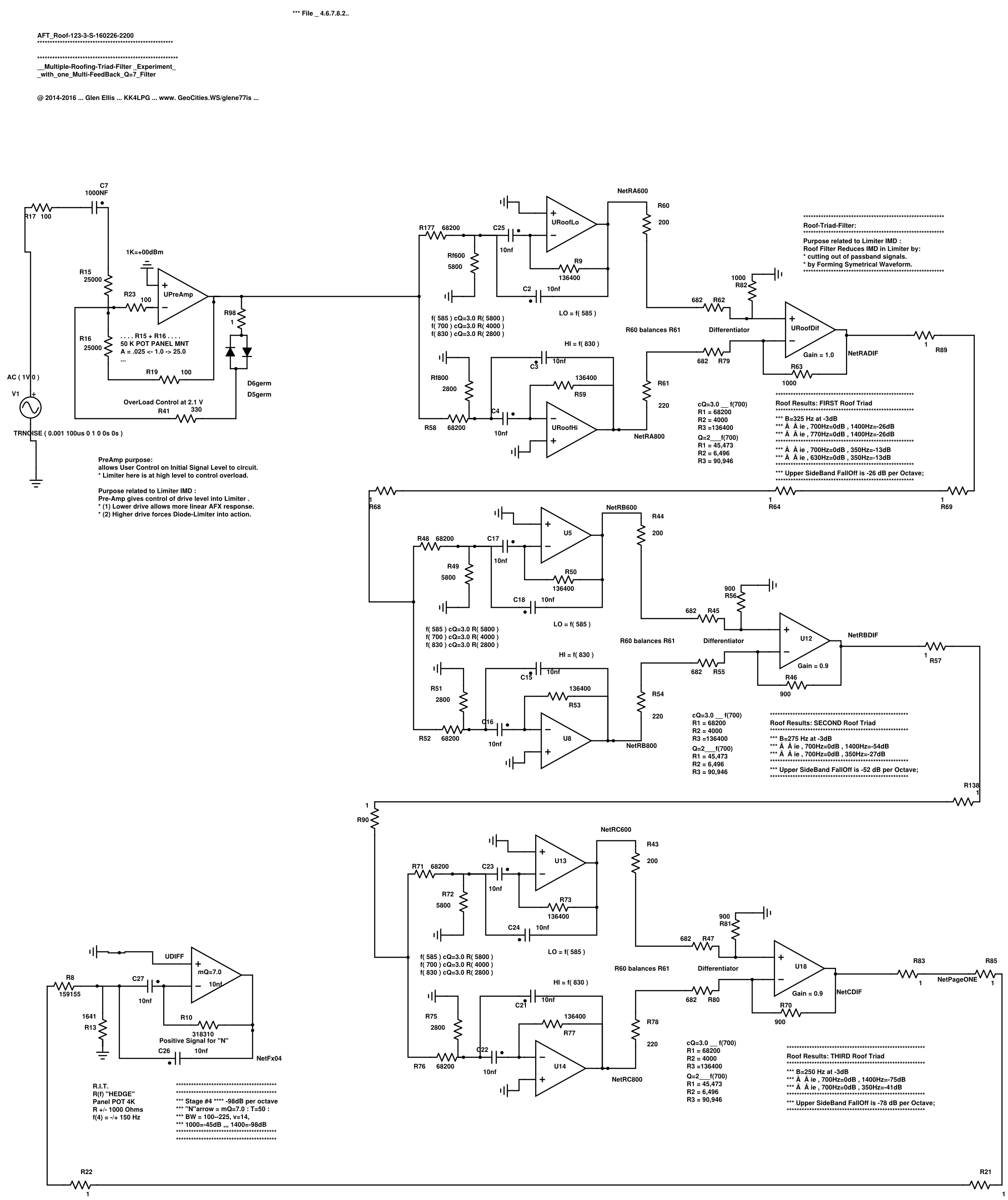
******** The Triple Roof-Triad-Differential_Filter *******************
*** Vsignal=TR(noise) from ngSPICE and f(center)=700Hz
*** Differentiated Signal is about 250Hz wide at -3dB
*** Sideband FallOff is -78 dB per octave
*** ie, 700 Hz = 0 dB and 1400 Hz = -78 dB
*** Stop-Band = -78 dB to the limits
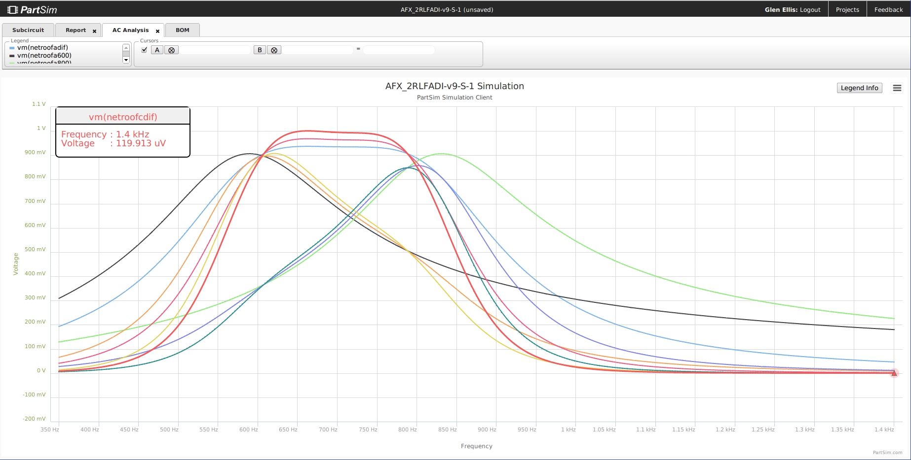
*** Triple-Roof Filter : Sideband FallOff is -78 dB per octave
*** ie, 700 Hz = 0 dB and 1400 Hz = -78 dB
*** Stop-Band = -78 dB to the limits ( red trace ).
********************************************************************************
********************************************************************************
********************************************************************************
*** Preliminary Info about 'WHY' to use a Roofing Filter :
*** Transient Analysis showing Time Domain Phase data.
*** The RED is the signal noise injected for testing.
*** The Noise signal has random frequencies, very little 700 Hz C.W. signal.
*** The Roof filtering action is the smaller smooth trace.
*** This is the most basic idea behind the Single-Roof-Triad-Differential_Filter.
*** Roofing Filter controls Common Mode noise from the radio band and minimizes IMD in the Limiter
*** by producing Symetrical Waveform Signal.
*** Center band 300 Hz wide is free from narrow-band phase-shift/phase-delay.
*** Only Sidebands > 300 Hz center band are supressed to minimize Limiter InterModulation-Distortion (IMD). 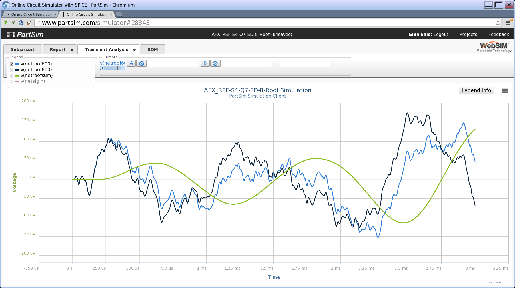
********************************************************************************************
*** possible First Reason for using a Roof Filter:
*** Notice that the aSymetrical Noise signal is converted into a Symetrical Signal.
*** Symetrical signals produce far less InterModulation Distortion during Hard Limiter Action.
*** The Noise Signal is Common Mode and is canceled by the Differentiator.
*** See the full "AFX" circuit for the context of this Roofing Function.
*** Black and Blue trace is Random noise signal injecting common-mode signals.
*** These have been filtered by the 600Hz and 800Hz filters.
*** The Green trace is the Differentiated C.W. signal Vout without any Common Mode Noise.
*** The Green trace shows the combined 600Hz and 800Hz signals centering on 700Hz.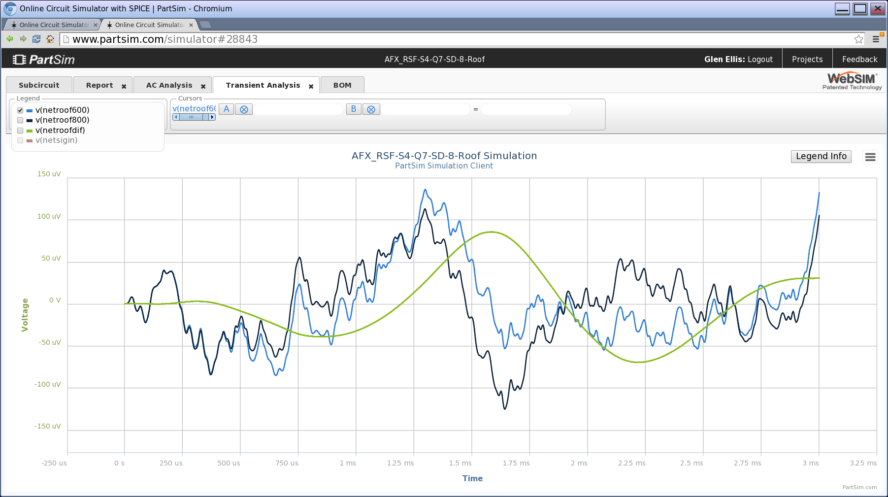
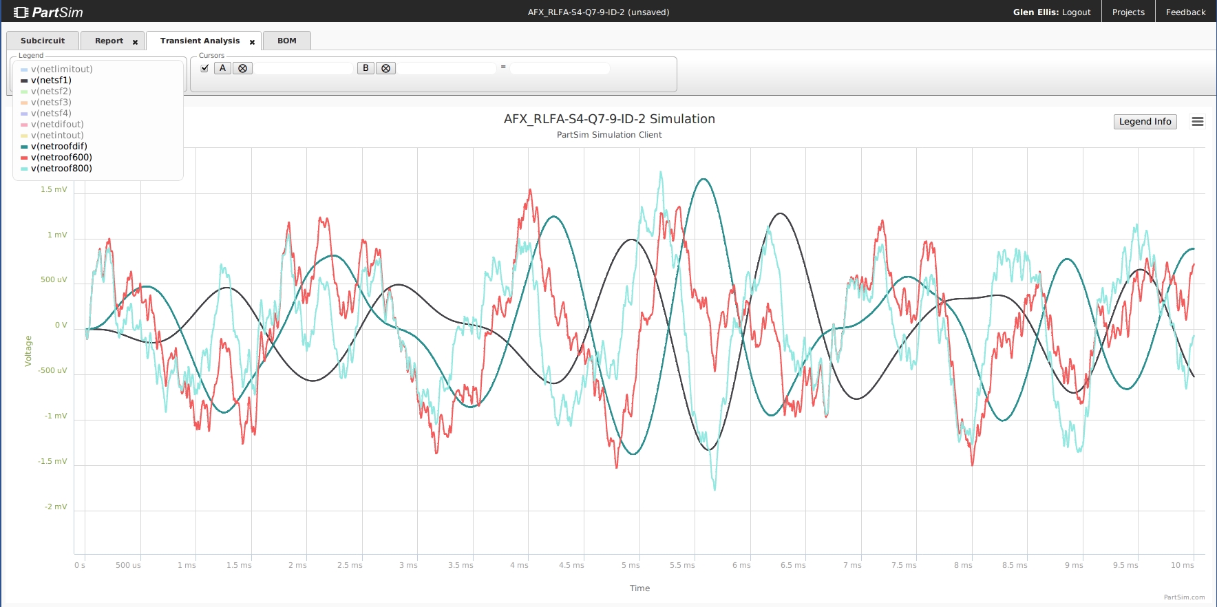
*** Notice that the aSymetrical Noise signal is converted into a Symetrical Signal, balanced on 0V line and phase-aligned.
*** This is the same action that occurs in an All-Pass Filter; (here we eliminate the need of AllPass Stages).
*** Symetrical signals produce far less InterModulation Distortion during Hard Limiter Action.
*** See the full "AFX" circuit for the context of this Roofing Function.
********************************************************************************************
*** possible Second Reason for using a Roof Filter :
*** Differentiated Signal is about 300Hz wide at -3dB
*** which attentuates much Out-Of-BandPass signal, and possible overload IMD.
*** The wide BandPass has little affect on the Phase Relations of the central signals.
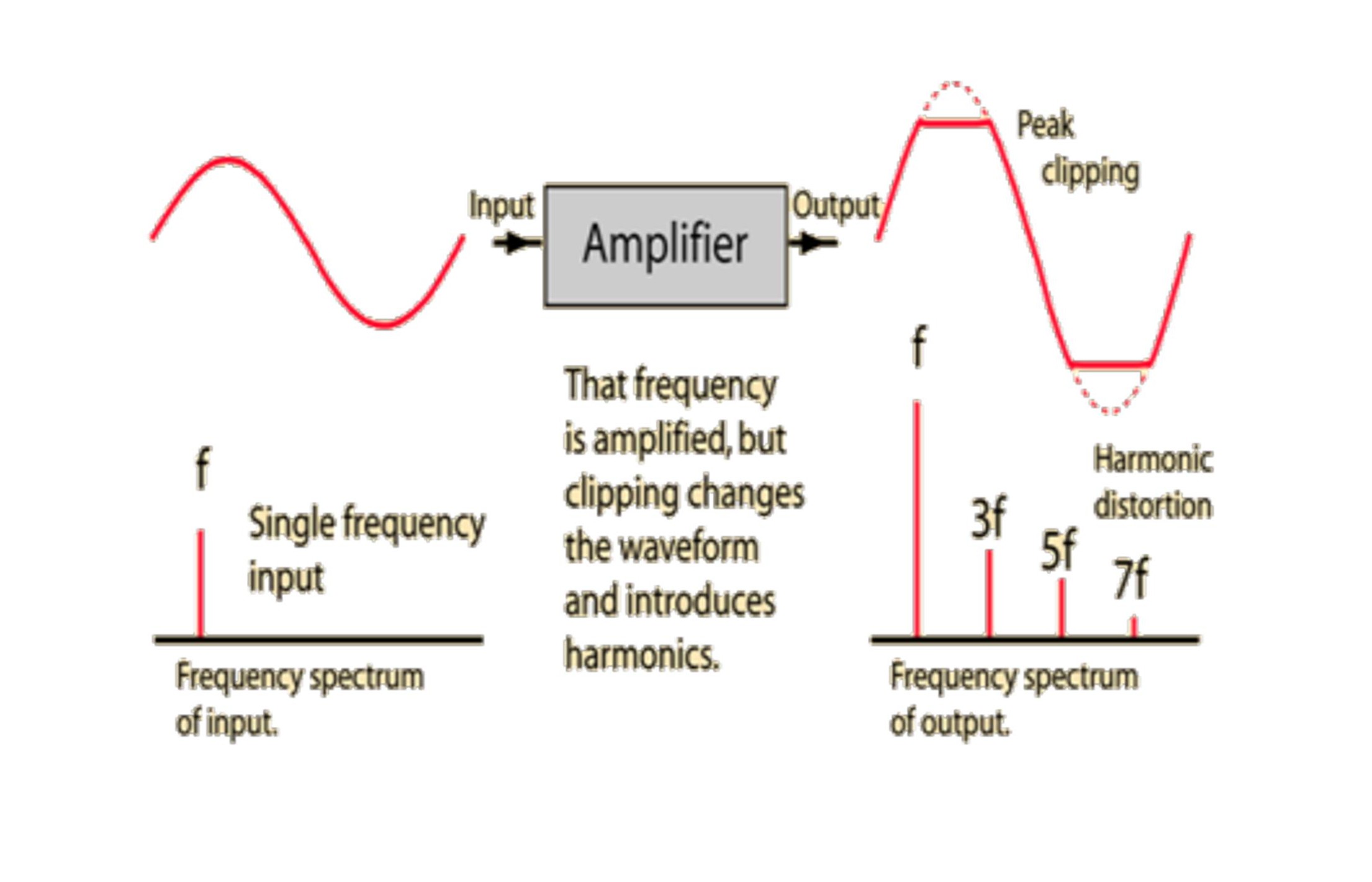 Example of Inter-Modulation Distortion Effects
 ***********************************************************************************************
Do "Exotic" amplifiers even exist? - ResearchGate.
Available from: https://www.researchgate.net/post/Do_Exotic_amplifiers_even_exist
[accessed Dec 17, 2015].
( Regarding a query about final purpose of the Roofing Triad Filter )
First off, the preliminary stage is only gain control.
The Lower Filter is tuned to 600 Hz. See schematic.
The Higher Filter is tuned to 800 Hz. See schematic.
These two different signals are Subtracted by the Differential Amp.
(1) This Roofing Filter circuit produces a flat-topped ( 300 Hz @ -3dB ) signal
with sideband attenuation of -27 dB per Octave.
(2) The Roofing Signal out has symetrical waveform.
That is the most obvious function, for this one triad stage.
This Roofing and the total of the AFX project functions
within the context of Amateur Radio C.W. (morse-code) operations,
to produce narrow pass-band filtering, making use of analog phase-sensitive filters.
Looking at the whole AFX circuit,
I am working with phase relations amongst signals that are surrounding 700Hz,
feeding an Active Log-Limiter, and four MFB bandpass filters, and a final Differential untuned-filter.
The overall AFX circuit object is
to produce a Double-Notched Narrow-passband Audio Signal,
centered on 700Hz.
The Roofing Filter is for clarity in CW operations,
where in I need to reduce the wide sideband signals,
and form symetrical waveforms for the Limiter.
The quad filter and Differential are used to produce a Narrow bandpass,
We need to subtract two particular phase related signals
to produce double -48dB notches at plus/minus 230 Hz
around 700 Hz.
The above numbers are aprox. to simplify the description.
I hope the two attached plots will assist directly.
I use the larger AFX circuit daily 'on the air',
and there is a simpler version we put on the market.
The whole project is at my website linked below.
We found this to be an interesting and effective analog project,
with clarifying help by Barrie.
Glen Ellis
added: attached a schematic with more readable detail.
I might note that i did run a series of experiments using analog sequential circuits
comprised basically of the same high and low filters,
and also using a simple Summing stage, and also a simple MFB Q=2 passband at 700Hz
... but found much better results using current parallel + differential 'triad' filter. Much of this is on my website.
The use of the differential stage and the phase-sensitive approach has intrigued me
and caused me to stop and 'put on the robes of the electron' as Barrie describes the intuitive analysis.
The concepts involved were not immediately apparent to me, and I had little descriptive math, and no models to guide,
from my readings, to aid in this.
The project as part of a long term interest, with many approaches designed, Spiced, and constructed,
and tested with real-time C.W. on-the-air contacts and critical O'scope monitored listening.
Do "Exotic" amplifiers even exist? - ResearchGate.
Available from: https://www.researchgate.net/post/Do_Exotic_amplifiers_even_exist
[accessed Dec 17, 2015].