GC_ET_AFX_CW_FiltDIQ.html
2021-07-18 10:38:25
"AFX" the post-Filter Phase Sensitive circuit :
*****************************************************************************************
Note: in the following diagrams, R2 is the R(freq) for adjusting f(center).
ie, R2 is at the source/drain connected to ground, for MFB resonant node.
Note: the -1dB level is equivalent to 900 mV level and barely audible.
Note: the -3dB level is equivalent to 700 mV level in these Bode Plots.
Note: [ (BW@-12dB - BW@-3dB )/9dB labeled as : "v" = slope of best fit ]
***************************************************************************************************************************************************************************
*** Goal: "N"arrow and "W"ide passband signals.
"N" and "W" passbands are achieved ,
with Roofing Filters,
with Quad MFB filters,
with the Differential and Integration stages.
(1) Differential produces "N"arrow double-notched passband.
* Stage 'UDIF' ( DIFFerentiating Fx01 with Fx04 ) to produce a "N"arrow double-notched signal.
(2) Integration produces "W"ide Flat-Topped Steep Skirt passband.
* Stage 'UINT' ( INTEgrating #3 negative and #4 positive signals ) to produce a "W"ide flat-top steep sided signal.
Note: Below specs are from PartSIM, and the schematics / plots are from ngSPICE.
Note: Author did the initial build-up on ProtoBoards, and measurements compare favorably.
Note: Author has used variations of these circuits since 2013 in his Amateur Radio Station.
These specs show both the "cQ" (calculated "Q" specific to each designed stage) ,
and the "mQ" (measured "Q" as it accumulates progressively through the circuit) .
*****************************************************************************************
*** the reader should note these filter characteristics :
*** The DIFFerential and INTEgration Filter Stages have passband curves that are NOT Gaussian curves.
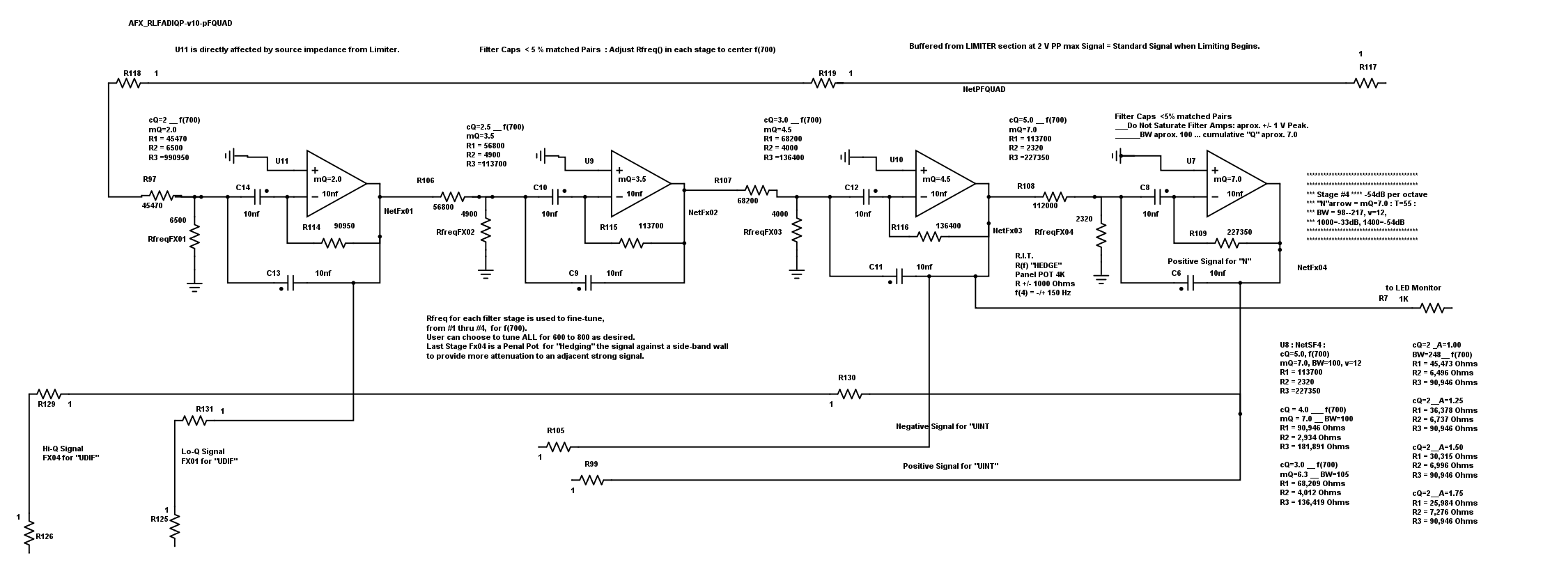
**** This is the QUAD MFB FILTER plus DIF and INT stages :
The filters are Fx01 , Fx02 , Fx03 , Fx04 .
The calculated 'Q' are Q=2.0 , Q=2.5 , Q=3.0 , Q=5.0 ( calculated )
The measured 'Q' are Q=2.0 , Q=3.5 , Q=4.5 , Q=7.0 ( cumulative measured )
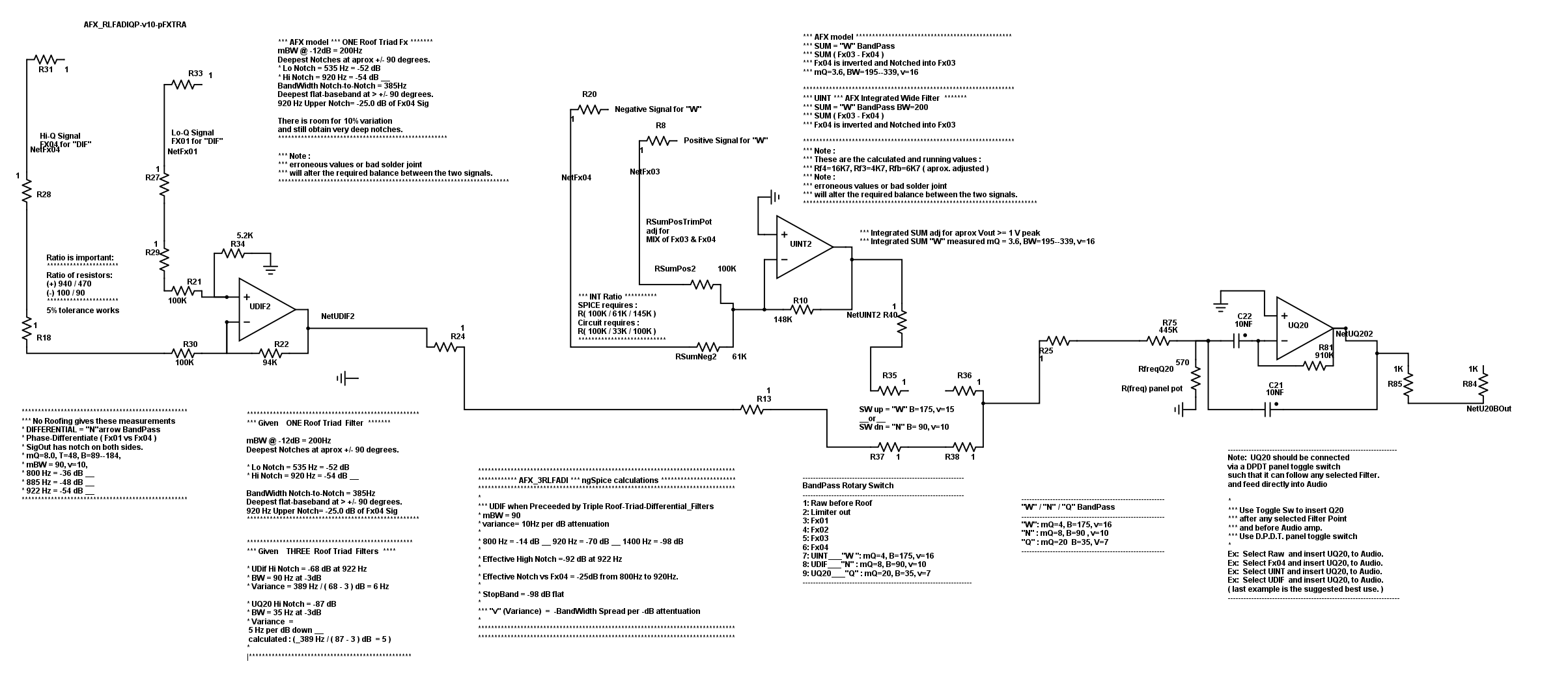
**** These are the DIF and INT stages Plus the Q20 sharp stage :
*********************************************************************
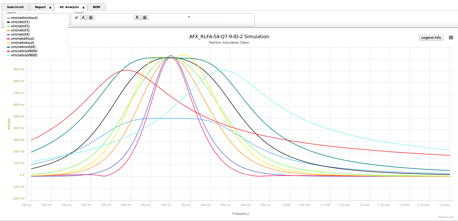
*** Notes on Bode for DIFFerential "N" and INTEgration "W"
*** Differentiated "N"arrow is double Notched.
*** Integrated "W"ide is flat topped.
***************************************************************************
*** DIF stage operates by subtracting : Fx01 - Fx04
*** and produces Notches which are -27dB below Fx04
*** effective Notch Depth = -48 dB
*** BW=86--190___v=12
*** Notch=533 @ -50dB
*** Notch=920 @ -50-dB
*** StopBand= -48dB
****************************************************************************
*** INT stage operates by summing Fx03+Fx04
*** BW=176--369___v=-22
*** StopBand = -19dB to -42dB
************************************************************************************************************************
**********************************************************************************************************************
Below:
Narrow Differential signal is BLUE and Wide Integrated signal is BLACK 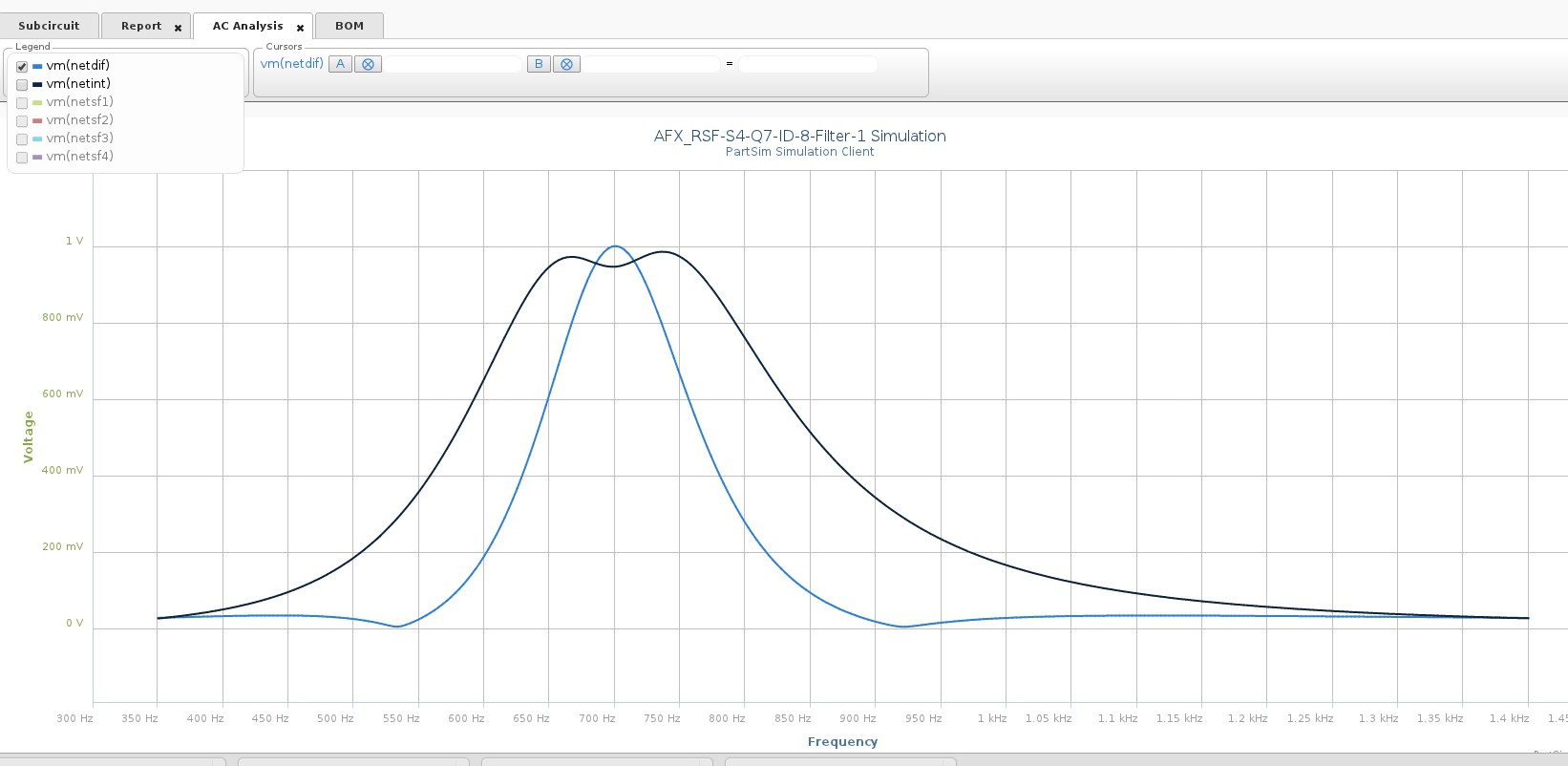
*********************************************************************************************
*** Below : early design with NO Roofing-Filter :
*** the Bode for Fx01 (black), Fx04 (blue), and the Dif "N" (red) .
*** At 925Hz , the Dif "N" (red) versus Fx04 (blue) is -27 dB.
*** This is a log scale plot so the real curve difference is difficult to visualize. 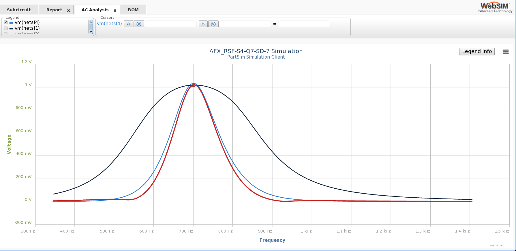
Magnitude Plot of Dual-Notch Effect Goal is Ideal Brick-Wall Effect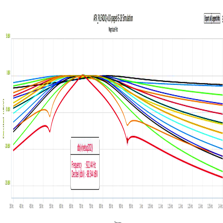
*******************************************************************************************************
Below:
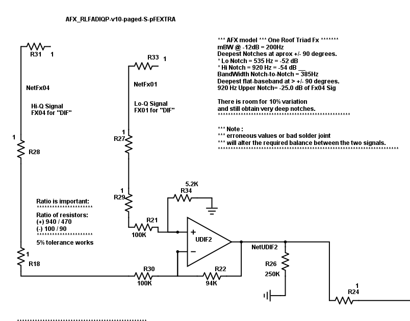
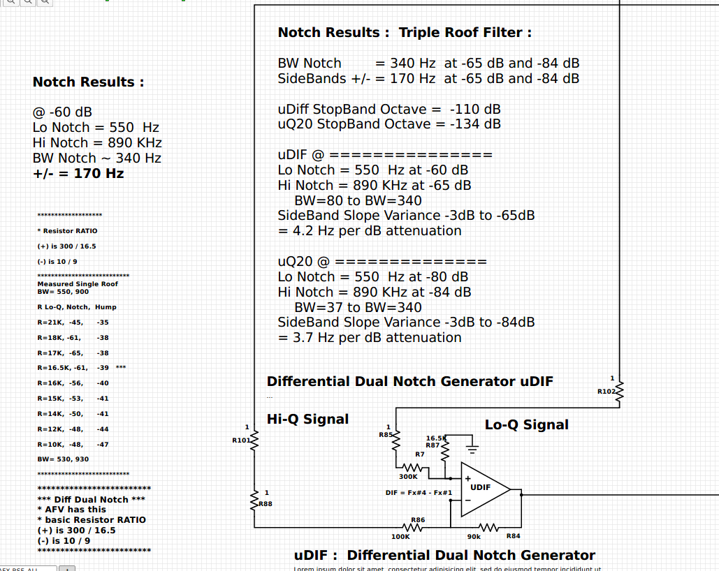
*** "UDIF" NARROW DIFferential stage details
*** where Filter#4 (mQ=7.0) is subtracted from Filter#1 (mQ=2.0)
*** easily producing dual -48 dB notches at aprox. +/- 90 degrees :
*** StopBand is aprox. -45 dB to the limits
*** Notch Band-Width is aprox. 350Hz.
*** Experiments to Narrow the Notch Band-Width tighter are ( here ).
*** Ratio of Resistors is important but not critical :
[ (+) 300K : 15.9K and (-) 100K : 100K ]
*** notice that a very small amount of Fx01 signal is used, 5% tolerance.
*** Ratio depends on the f(LoNotch) and f(HiNotch), which has been tested at 535 & 935 and variations.
*** BandWidth of Dual-Notches is Dependent on the Q and the Q-spread of the Quad-Filters.
*** Quad-Filters with a Same Q=3 for all four filters produce 530 & 930 , and work very well.
*** Principle effect will be noticed on adjacent very strong signals, where 1000 W can be reduced to sound like 1 Watt.
****************************************************************************************************
Below:
WIDE: "uINT" stage is a INTegration of Fx#3 positive and Fx#4 negative.
Still in development, but earlier versions have worked well, according to the O'scope.
Ear can hardly hear the effect.
Functionally, Fx04 is an inverted signal to Fx03,
and both are INTegrated (summed) by the 'uINT' OpAmp.
Fx04 is inverted and a 10% signal is used to form a notch into Fx03.
Notice that a small amount of Fx04 is used to compress the Fx03 peak.
*** The Ratio of Resistors is important.
This produces a "W"ide signal with a very broad top and steep skirts.
This Bode shows a 1/2 dB dip in the passband ( below audibility ).
“W” / “N” via a single Switch.
#6 INT stage produces Very Broad Top of 175 Hz.
#6 INT stage produces a sideband skirt nearly as steep as the "N" stage.
Final INTegrated stage "W"ide ------------ mQ=4, BW=175, v=16, K=-24
SPICE requires : R( 100K / 61K / 145K )
Constructed circuit requires : R( 100K / 33K / 100K ) 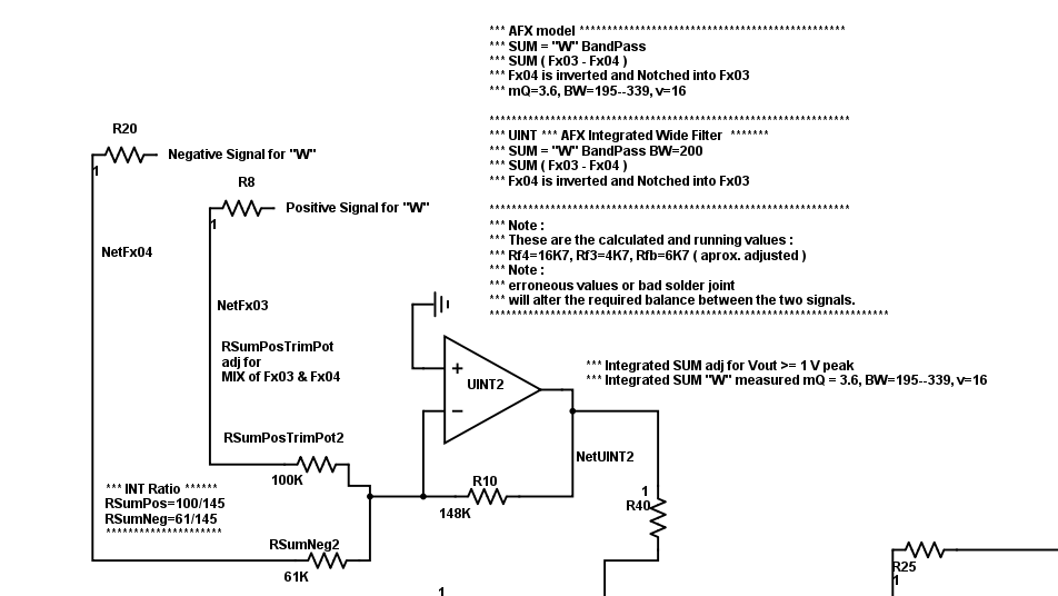
***************************************************************************************************
*** Bode for ALL complex waveforms , as described so far. 
**********************************************************************
*** Bode for Sum"W", Dif"N".
*** #5 UDIF and #6 UINT stages are the Differentiating and Integrating stages.
*** These are untuned stages, and produce a very Non-Gausian BandPass.
*** Bode for Fx03, Fx04, Summed to produce the "W"ide signal.
*** "N"arrow Differential signal is "blue" with double notches,
*** formed by subtracting Fx01 and Fx04.
*** "W"ide signal is the red flat-topped trace.

**********************************************************************************************************************************************************************************************
**********************************************************
**********************************************************
*** NOTE about the special DIF and INT stage characteristics :
*** The DIFFerentiantial and INTegration stages do NOT generate gausian curves.
*** The DIF and INT stages combine two signals to produce non-Gausian curves.
*** The DIF and INT stages are NOT tuned resonant filter circuits.
*** The DIF and INT stages are Phase Sensitive Operational Circuits,
receiving two signals, operating, and producing a single signal out.
*** The INT stage produces a "W"ide signal, with a flat top, and steep side-bands.
*** The DIF stage produces a "N"arrow signal, with dual notches surrounding 700Hz
*** Graphical Concept for the Dual-Notches 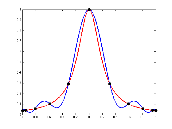
*** Where the wave-forms cross,
there is zero difference in amplitude,
and the Differential OPA produces a Notch !
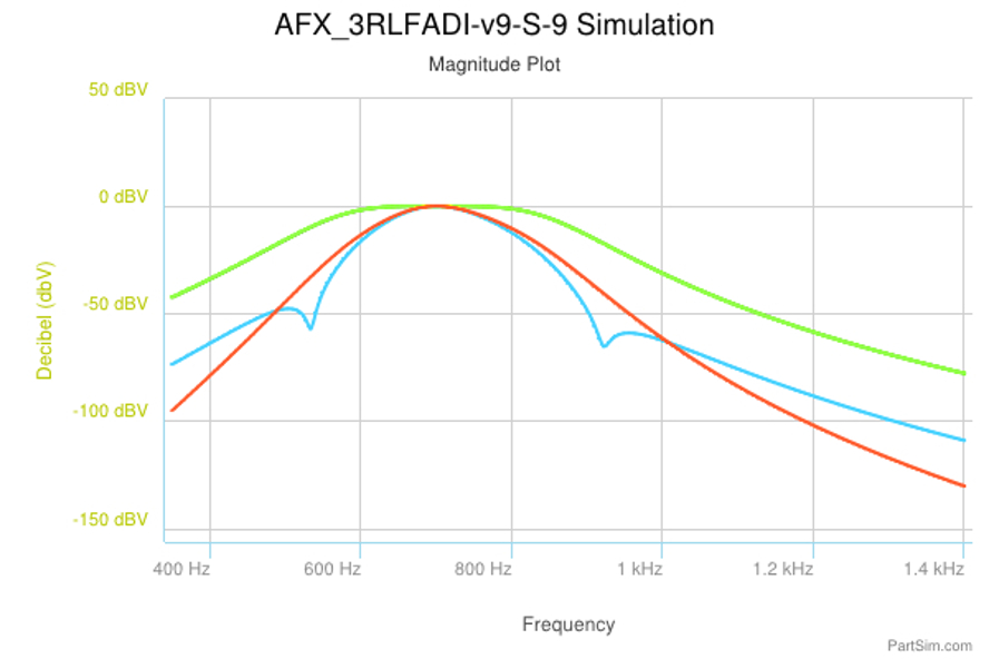
*** Below is a "Magnitude Plot" which emphasizes the dB relations.
**********************************************************************************************

*********************************************************************************************
*** COMBINING Filter#4 with UDIFferential dual-notch with Sharp Q20 stage ***
*** Below is a "Magnitude Plot" which emphasizes the dB relations.
Green trace is "roof"
Red trace is "Filter #4 "
Blue trace is "Dual-Notch"

*** Below is a "Magnitude Plot" which emphasizes the dB relations.
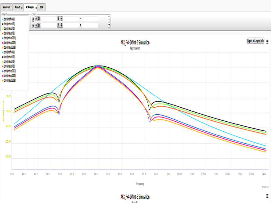
*** Green Fx04 + Orange Dif + Blue Q20 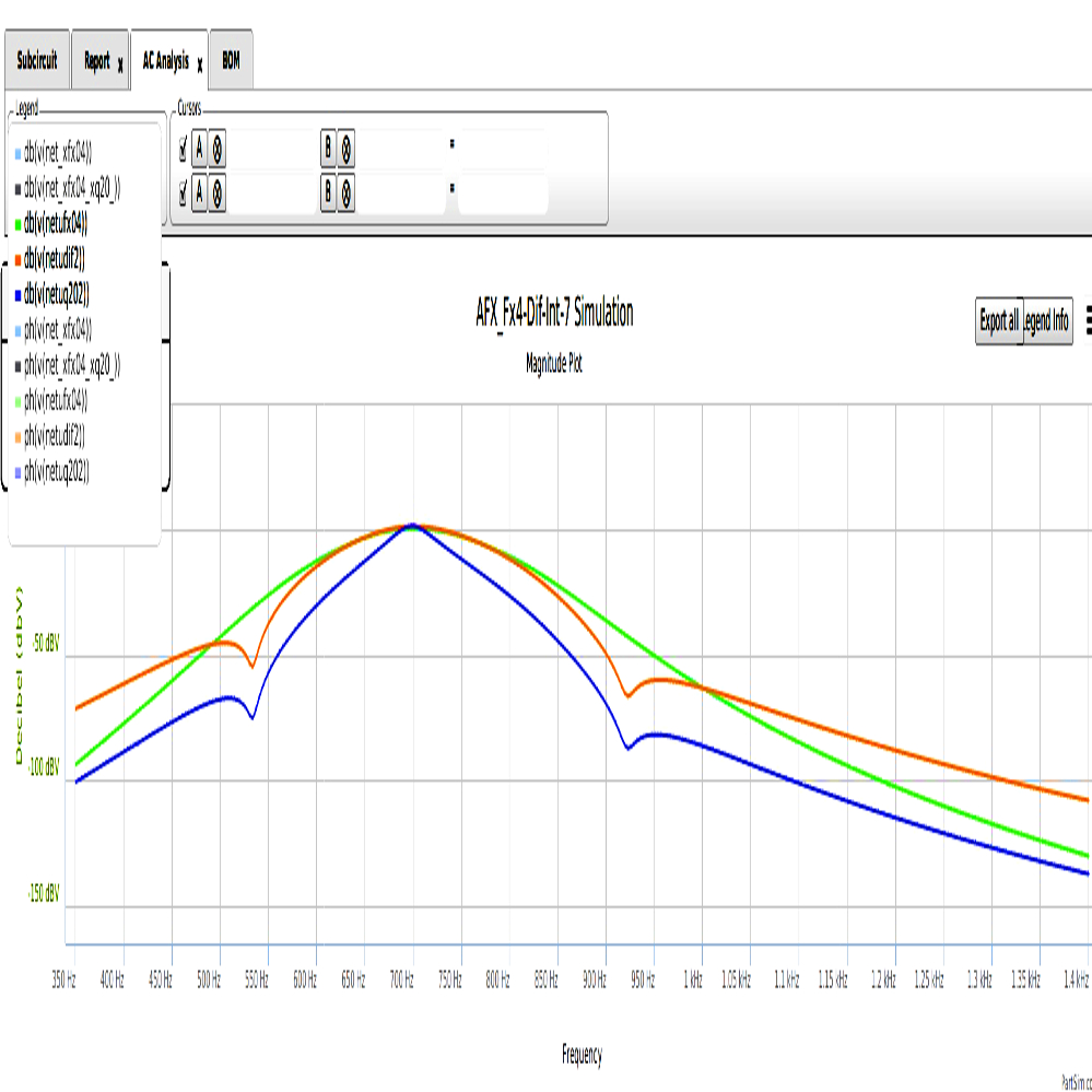

*** Triples are from DIF Stage at +/- 20 % component specs.
*** upper-wide Blue Fx04 vs. variable-Dif vs. variable-Q20
*** which demonstrates component specification tolerance !!!
*** Q20 stage produces this Bode plot :
*** note that the Q20 sidebands have a variance of 7 ( ie, BandWidth spreads by 7 Hz per -db attenuation !!! )
*** Narrow BLUE is the UINT stage ... Narrow BLACK is Q20 with stop-band => -98 dB !
*** has NO dual-notch !
*** Int vs Q20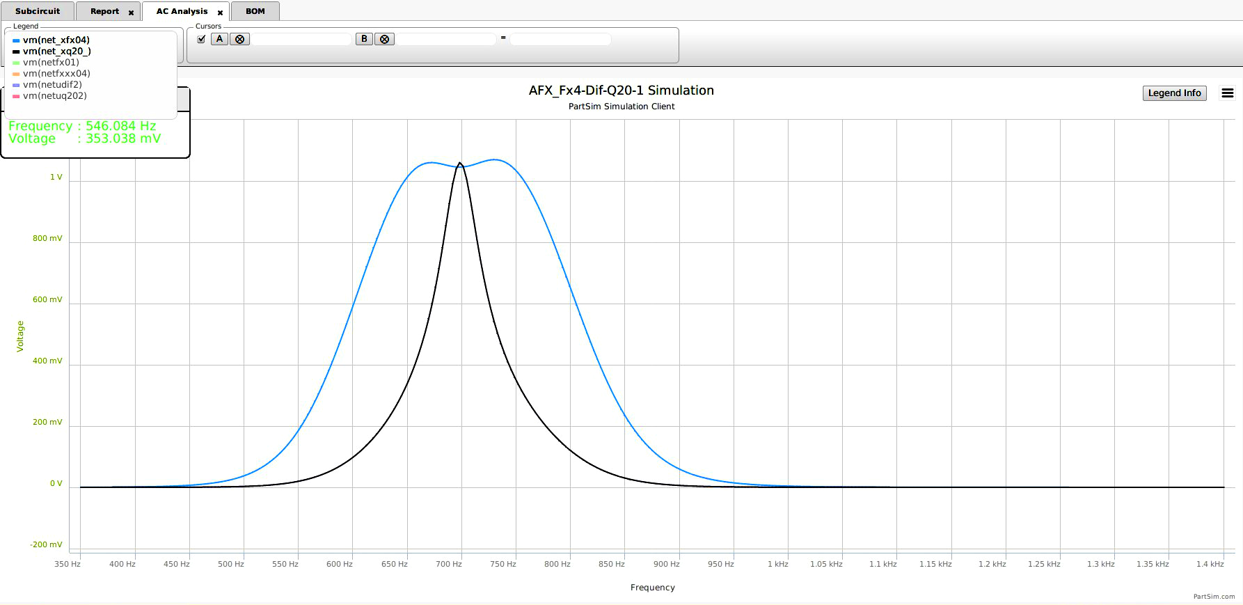
*** Future Development plots taken from current proto-type tests ***
*** Fx04 + Q20 is not so good. 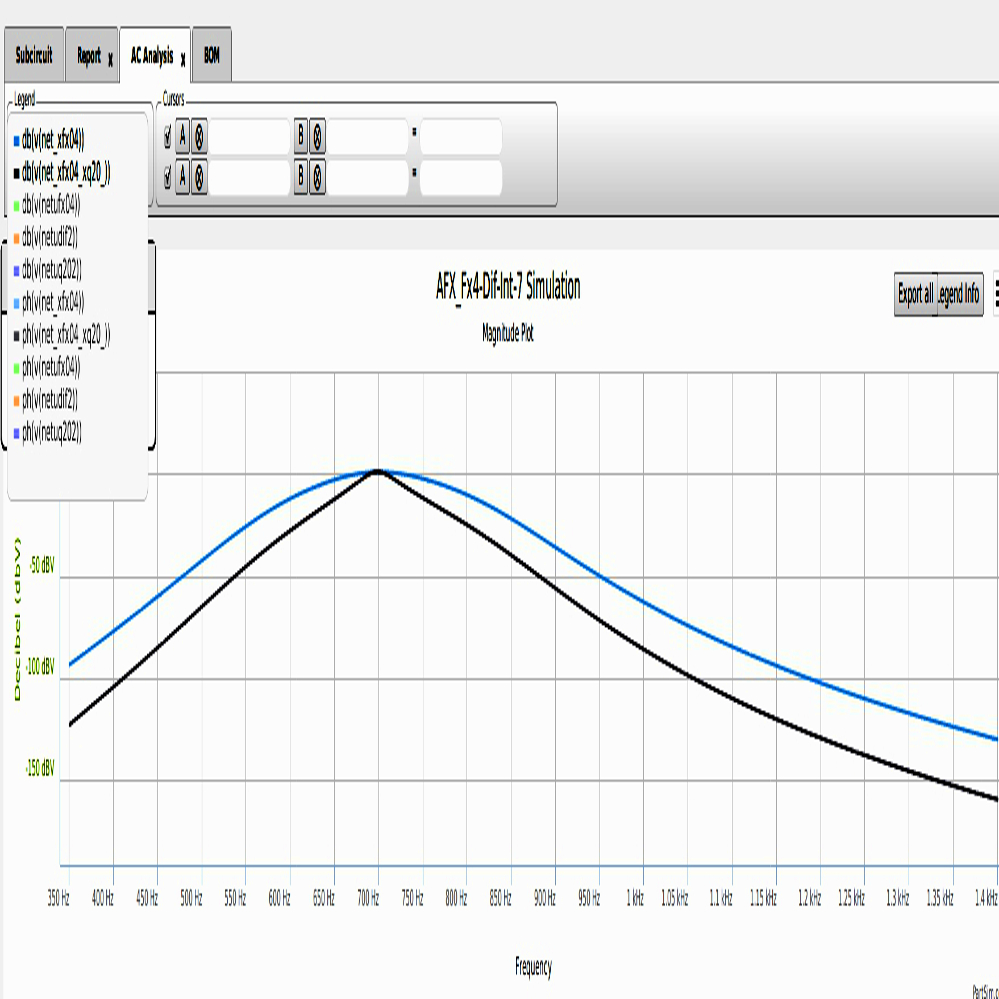
*********************************************************************************************************************************************
These are the author's AFX core Narrow Filter Circuits:
(*) the uDIF Differential Narrow Dual-Notch
(*) the very Narrow Q20 sharp filter with variable f(0).
**************************************************************************************************************