 Analog Active-Log-Limiter
 GC_ET_AFX_CW_Limiter.html
2021-01-06 09:42:06
 Analog Active-Log-Limiter
***** Log-Limiter circuits based on personal designs from 1975,
******* tutored by
Dr. Joseph Laughter, Bio-Med-Instrumentation, University of TN, Memphis, TN.
*** (!) Frequently you will encounter the "Anti-Parallel Diode" . 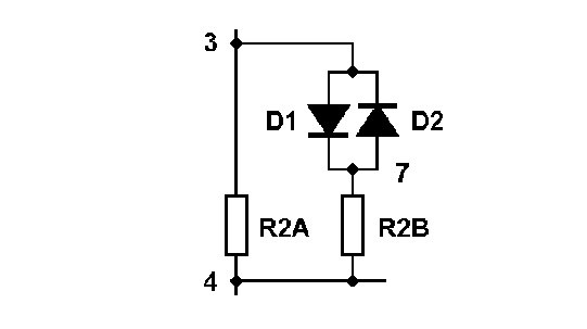
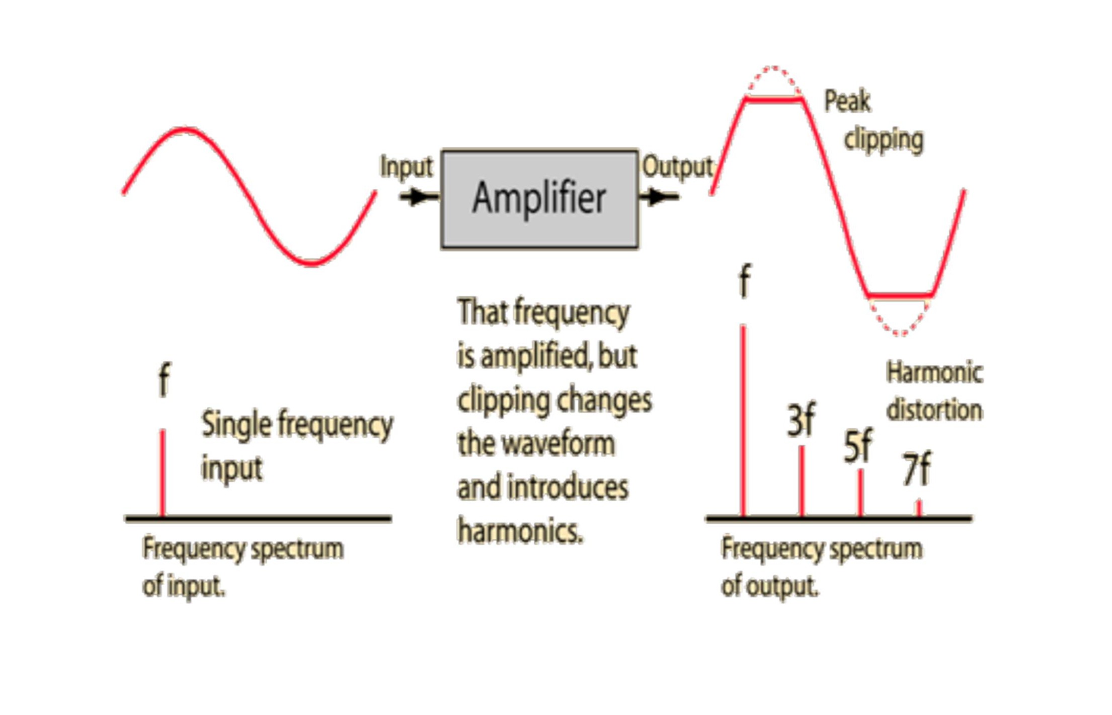
***
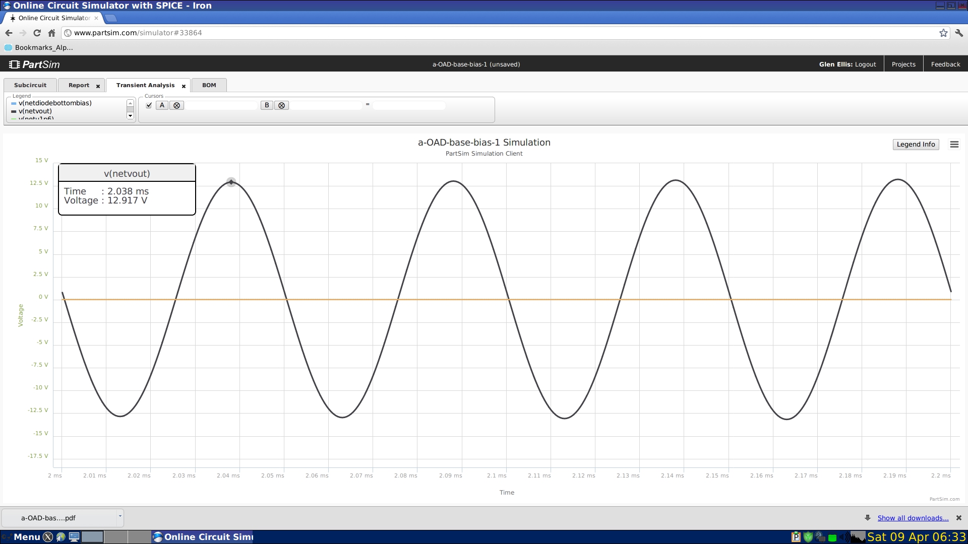
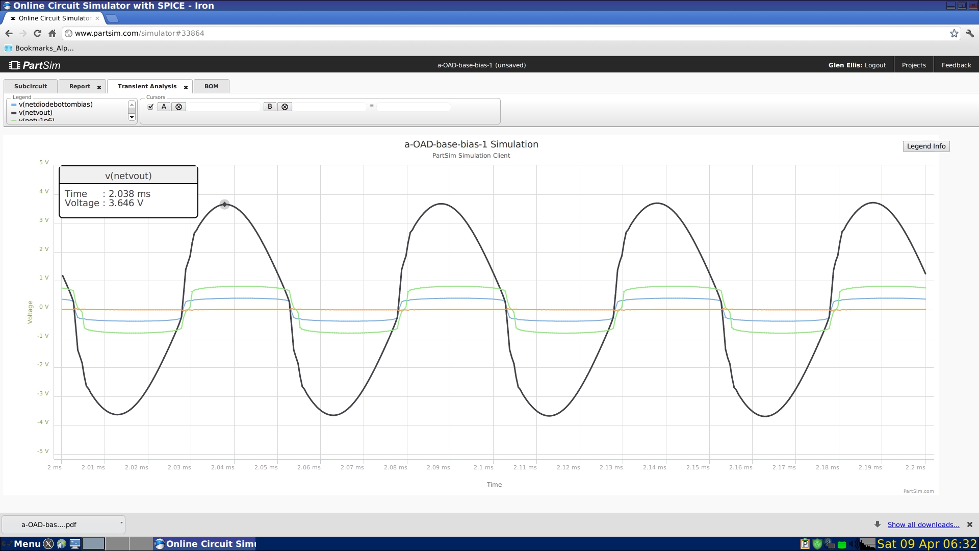
Below: Waveform display by Robert Keim, using silicon diodes.
Note that Diode Conduction (limiting) occurs at all levels of current flow.
The author has observed (measured) this from 1 micro-Volt upward in low impedance circuits.
( see author's Log-Amp circuits preseented on the " Notes from University of Tennessee page.
In common circuits, this effect is used from the 0.5V forward to 0.7V forward range.
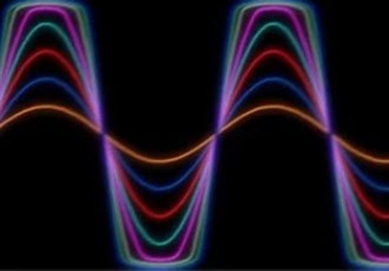
Image Shows graduated (+3dB) effects of driving the Limiter Diodes into Action.
On the top two levels, the limiting action (flat topping) is obvious.
On the top two levels, the diode turn-on generates obvious 3rd harmonic energy.
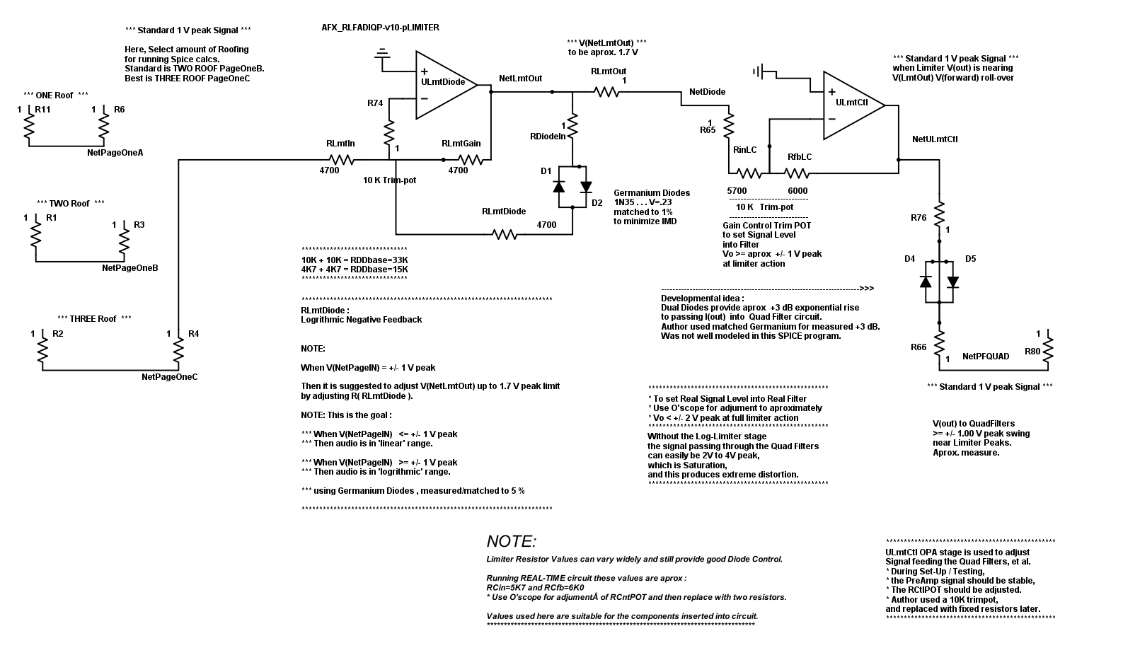
Here is some background on the author's Active Limiter circuit :
The first stage is a Pre-Amp with a wide-range gain control,
balancing the Rinput and the Rfeedback.
Since the signal is well above noise level at this point,
we wanted to prevent pop-corn noise from shocking the Roofing-Filter and Active-Limiter stage,
so we used a Log-Negative FeedBack function,
which acts strongly at about 1.7V , directly back into the Primary Vinput.
In General, the Negative FeedBack have an R(series).
The R(series) adds to the Diodes Internal-Resistance and Dynamic-Impedance,
...
Stated this way :
VF = VK log (IF/IS(T))
where real world "I"
always = V/(R+Dynamic-Impedance)
and we are adding to the "R" .
In tests, the resulting combination works well , just as described :
(1) R(series) linear resistance.
(2) Diode Internal-Resistance , dynamic and Logrithmic.
(3) Diode-Dynamic-Impedance from the PN junction, dynamic and Logrithmic.
All function together to lengthen the initial slope
but will still produce abrupt Roll-Over-the-Log at some upper level.
1 V signal works well into the Roof-Triad-Filter and also matches the Roll-Over in the Limiter.
More than 1.7V pushes the Signal into the Limiter enough to begin activating Limiter action.
1 V signal makes run time measurements between stages/modules easy to compare..
Same idea applies later in the dedicated Limiter Stage
with the log-Negative-Feed-Back diodes.
We did Transient plots to compare various combinations,
and did real circuit adjustments with O'scope to check.
Visualize this as Resistor-in-series-with-diodes feedback as :
(1) Resistive Negative-FeedBack
(2) with the diodes limiting any signal going above the R(fb) gain setting.
The soft-limiter effect is a human criteria we are chasing
and it is something that the ear/brain system can hear/read.
The Roof-Triad-Filter produces a very symetrical signal output,
and this reduces the IMD created when the Limiter section is active doing 'hard' limiting.
"Hard" limiting of an Asymetrical signal will produce more IMD and odd-harmonic distortion.
The stage for Monitoring the Limiter Action (LED (D3))
is not traced through SPICE since it does not transfer a signal.
In practice, the LM324 has about 50 Ohms Z(out)
and the voltage swing is limited to 4.5 V up or down by the chip itself ( +/- 6 V supply).
The monitoring LED runs OK as-is because
the Front to Back voltage ratings on the single LED
are tolerant of this level of push/pull voltage.
***

**************************************************************************************************
**************************************************************************************************
**************************************************************************************************
*** Test Circuit to show variations of the Linearized-Log Negative-FeedBack Method ***
**************************************************************************************************
*** below, the V(out) Limiter varies from 1.7V up to 2.24V. ***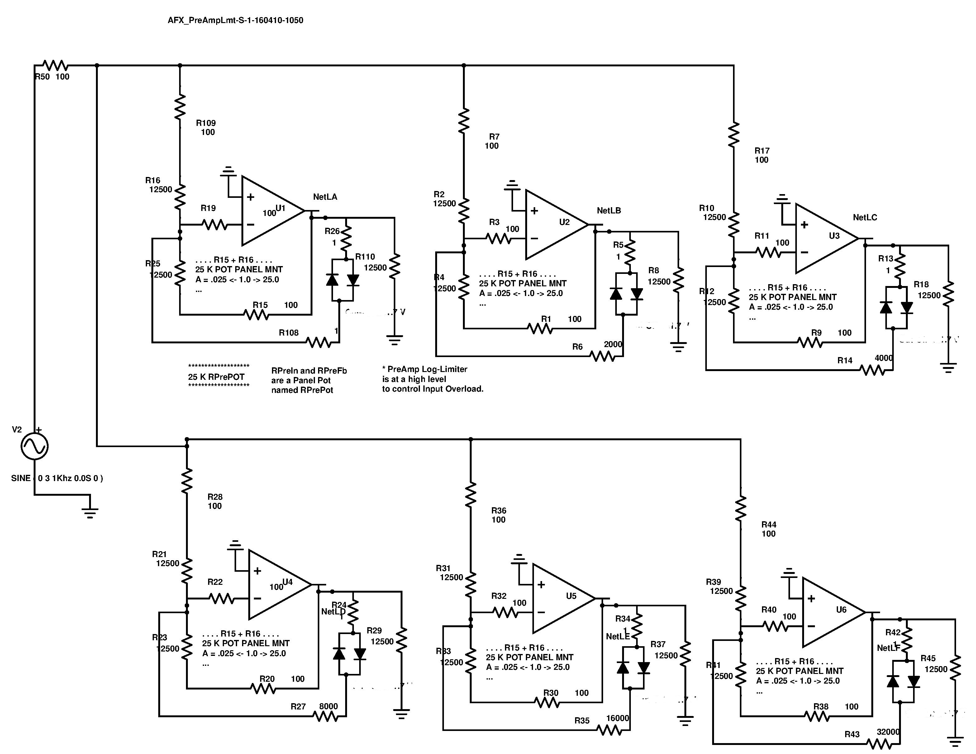
**********************************************************************************************************************
*** Below **********************************************
The Author's Pre-Amp includes an Active Log-Limiter,
whose Limit Level is based on the Gain of the OPA stage.
Gain is calculated by R(in) / R(feedback).
As the stage gain is adjusted, in normal usage,
the V(Limit-out) also changes.
The Non-Linear Limiter is altered by a Linear relation with Gain.
As Gain is increased, so the V(limit-log-out) also increases,
providing more head room for the possibly larger V(out) signal.
( Any possible pro/con to this is up for discussion. )
The attached Bode demonstrates the results of a full swing of gain from minimum to maximum.
Blue signal is V(in), and rainbow signals are various logs of the V(in) signal.
*** Given V(in) = 3V, the V(out)Limiter varies from 1.7V up to 2.124V. ***
We Published this in the thread "What is the secret of diode clippers?" - ResearchGate.
Available from: https://www.researchgate.net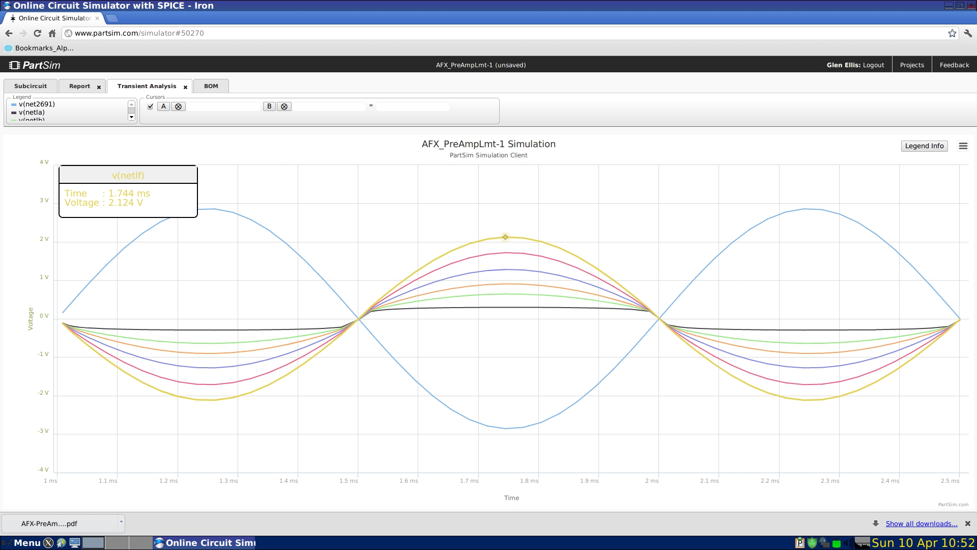
***************************************************************************
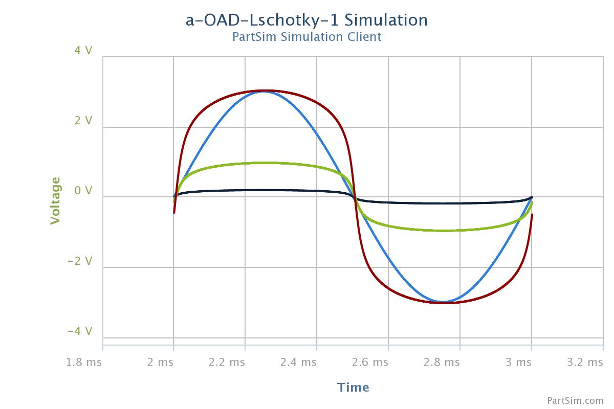
Below: these Bodes show the various types of diodes limiting signals and their natural shape.
Normalized to about 1V, as in actual use, which also aids in visualizing their effects.
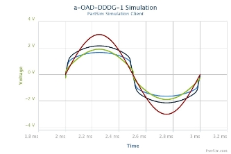
Vsignal is the dark-red trace at 3V,
Vdiodes are rainbow traces taken at V(out) and are in the 1V range.
Vdiodes are actually in the .23V to .60V range
and the circuit is adjusted to a standard 1V V(out) in the selected circuit prototyped.
Author's Spice traces :
optimized/normalized to normal 1V standard
so that the curve shape can be visually compared.
Silicon has as a sharper cut-off and Schottky has a more sloping cut-off.
The author selected the Germanium soft curve for use in AFX Limiter stage
because the characteristic curve could be measured and matching diodes selected in pairs.
Another research associate selected silicon (KC9ON) for our commercial production model.
The dark-red sine wave is the applied test signal.
Note: The sharp knee intermodulation effects are filtered out by he following BandPass Filters.

***************************************************************************************
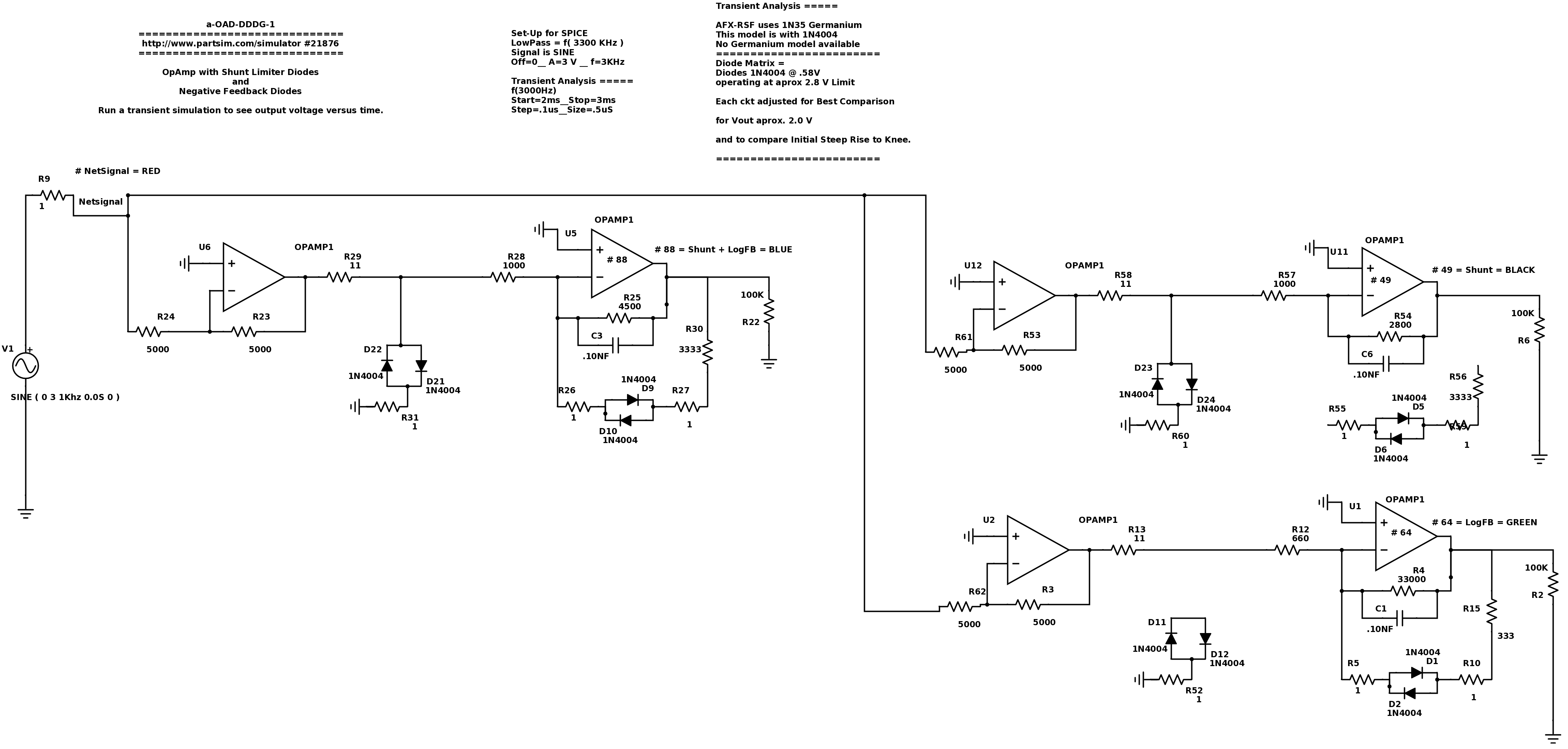
Author's Method of Studying and Comparing the Simple-Shunt and the Negative-FeedBack Limiters
*************************************************************************************************************************
*** Below : Normalized to the standard 1 V. Vsignal is 3V, and Vdiodes is actually in the .23 to .60 range.
*** In a real circuit the Vout is always normalized to some standard, such as 1V out Peak, by the user.
*** Each type of Diode has a different Vout curve, and here they are Normalized for easier visual comparison.
*** Black = Shunt only = soft knee
*** Blue = Shunt + Negative Feedback = softest knee and least IMD.
*** Green = Negative Feedback only = sharp knee and greatest IMD.
Traces are optimized to normal so that the curve shape can be visually compared.
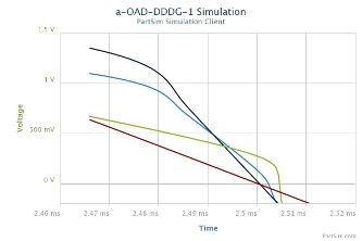
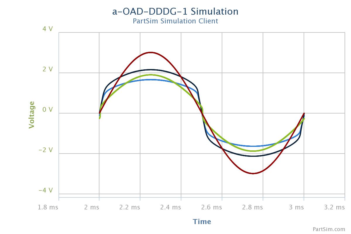
Above plots are normalized to the standard 1 V. Vsignal is 3V, and Vdiodes is actually in the .23 to .60 range.
********************************************************************************************************
Below:
Real world Turn-On curves are relative to actual current flowing in circuit and through diode.
(The authors have designed working circuits, using negative-feedback,
which work in the 10uA to 60uA range, using Germanium diodes. )
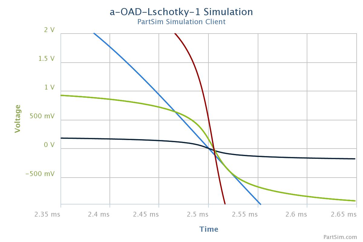
*** Results: Blue-trace Vinput from 0 to 0.250 V is handled in a linear manner Red-Trace.
*** Then the Diode Limiter turn-on curve is entered , causing progressive limiting .
*** Vinput from 0. V up to 0.250 V is very linear.
*** Vinput from 0.250 V up to max V is on the Log Curve.
**** end ****************************************************************************************************