 Advanced version
 AFX 'V'ariable
GC_ET_AFV.html
2021-01-15 12:00:02
*** (Home)
 Advanced version
AFX 'V'ariable
******* Goals achieved in AFX-V :
*** (1) Simpler design,
*** (2) Simpler construction,
*** (3) Simpler adjustment.
*** (4) better performance than original AFX design.
*** Designed from building-block modules
*** Designed to be very easy to tune to f(600) f(700) f(800) continuous.
*** Designed so that the f(0) for the Quad Filters can be easily adjusted by user.
*** Designed so that the Q=20 Sharp Filter is variable.
*** Designed so that the Dual-Notches are < -60 dB and the Stop-Band < -100 dB.
*** Design choices:
*** Simple repetitive application of Modified Deliyannis-Multi-FeedBack topology.
*** Multi-FeedBack topology was chosen because :
*** (1) input vs output impedances match well, loading is controlled.
*** (2) single resistor frequency control each stage.
*** (3) frequency adjustments alters gain by only the square-root of the f(change) .
*** (4) the Roof-Triad-Differential design provides superior side-band suppression.
*** and is wide enough to be very tolerant of component variations,
***********************************************************************
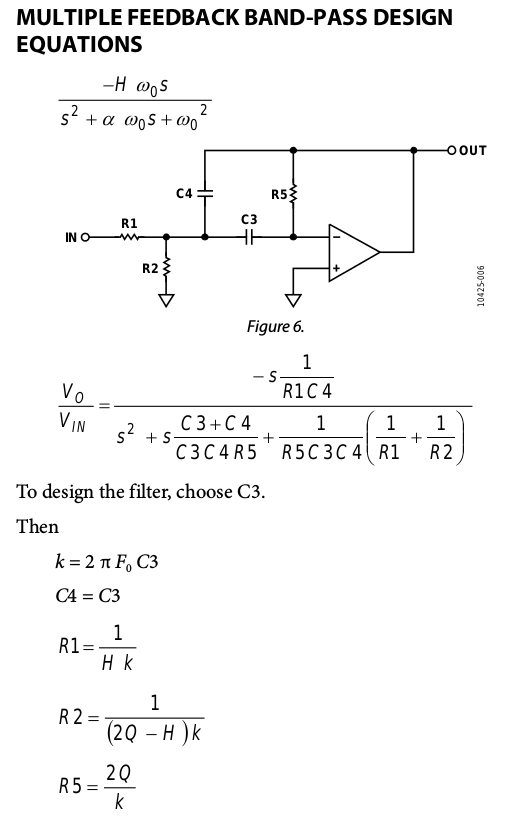 Just for reference.
***********************************************************************************************************************************************************
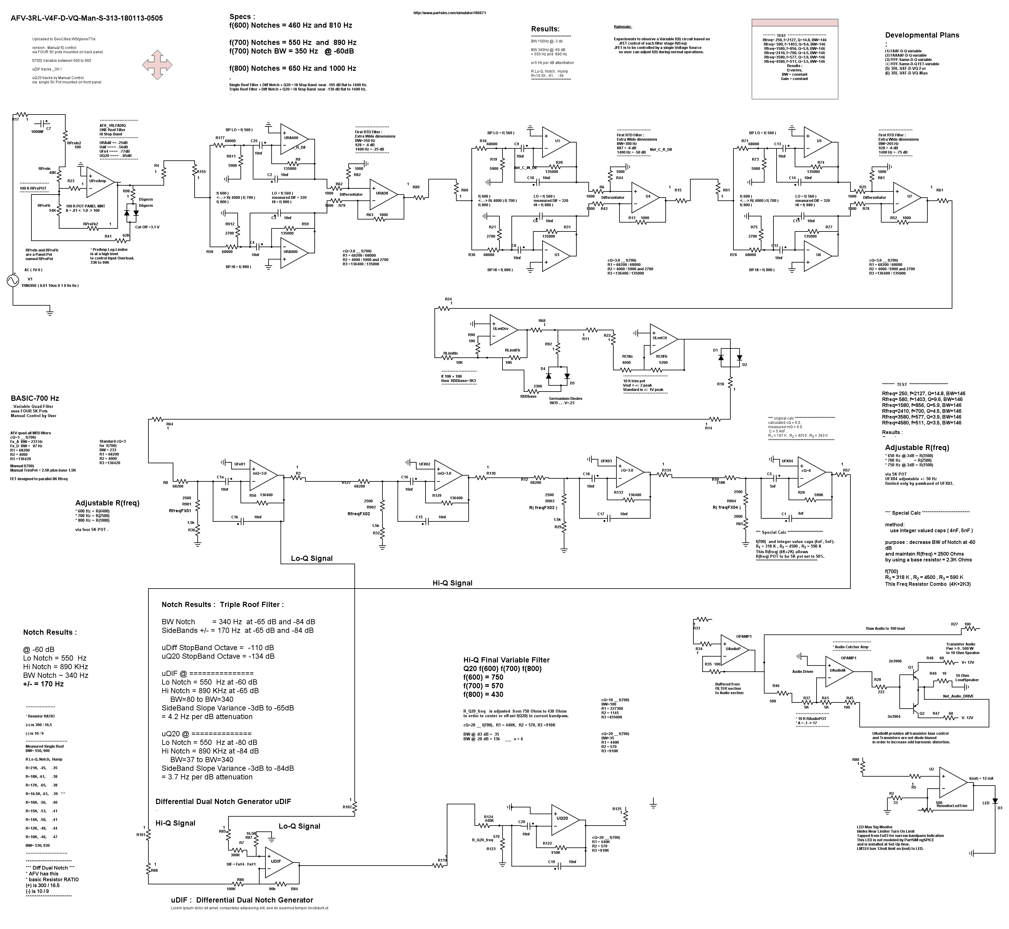
*** Below, "AFX-V-3rl-v4F-D-vQ-Fet"
the "AFX-V-3RL-v4F-D-vQ-Fet"
the Best-of-Class design
*** This circuit utilizes Three Triad-Roofing-Differential Filters .
*** The capabilities of the Triad-Roofing-Differential Filters are explored
on the { Roof Pages }.
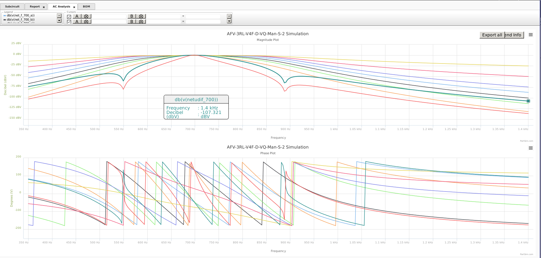
*** Dual-Notches are very Deep and Octave Stop-Band very low.
*** Main Filter f(0) is Variable 600 - 700 - 800 by user in real-time.
*** Sharp Q=20 filter is variable within the selected PassBand.
*** Here, the R(freq) is currently controlled by one R(freq) Pot, mounted on the front panel, for real-time control.
*** The Four FET controllers are driven by a single Voltage Source, controlled by a Panel Mounted Pot.
*** Front Panel Rotary Switch allows User to send any stage into the Audio Section.
*** Front Panel Switch enables FxQ20 to be used following any stage.
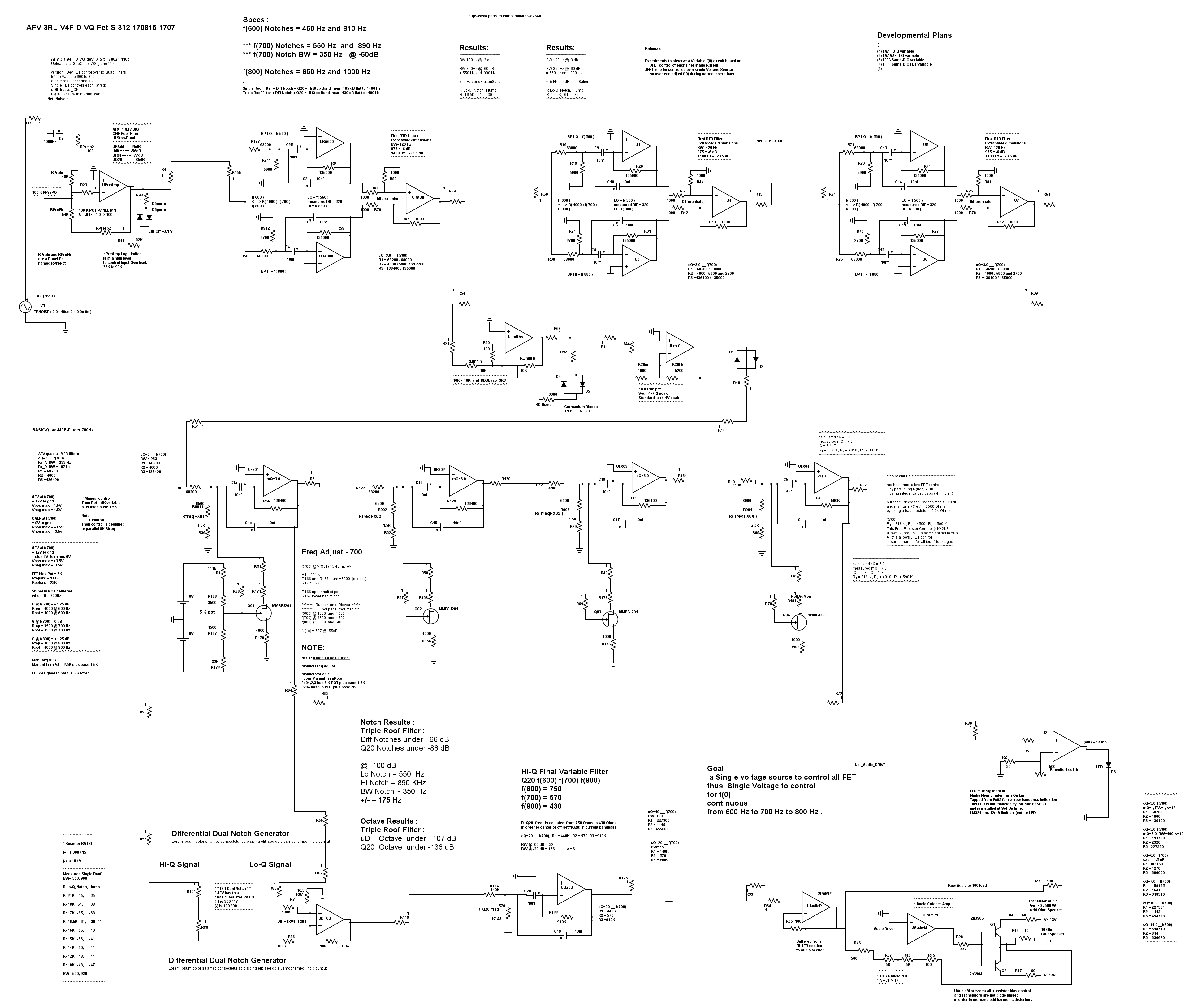
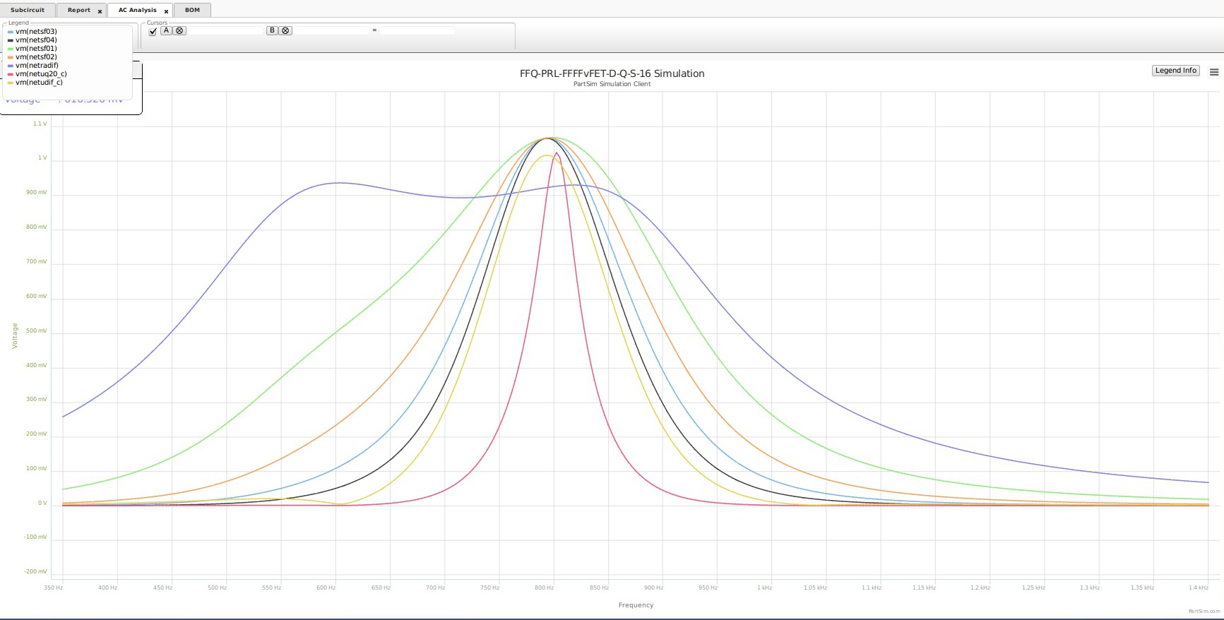
****"AFV-3RL-v4F-D-vQ-Fet" adjusted 600Hz , 700Hz , 800Hz
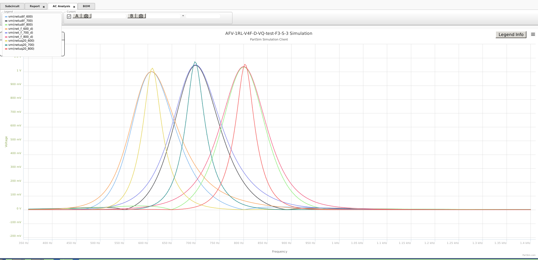
*********************************** Notice that the 600 - 700 - 800 waveforms have good BandPass shapes.
**** the very wide signal is the Roofing Filter Output, which will contain the variability of the central f() signal
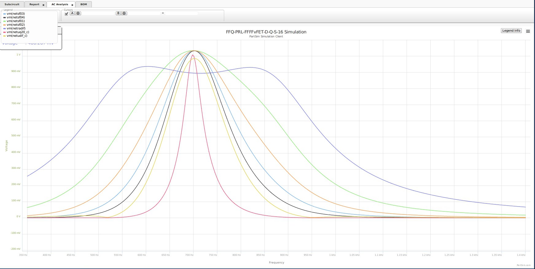
***** Notice that at all three frequencies, the peak amplitude of the final signals stay within 0.3 dB of the f(700) signal. 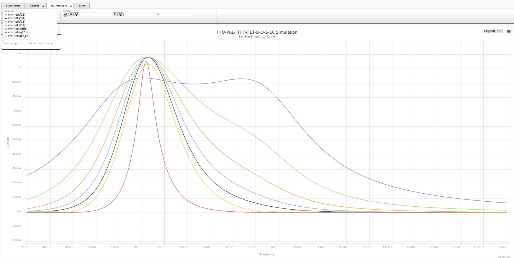
************************************************************************************
******* Magnitude Plot for AFV-3RL-v4F-D-vQ-Fet 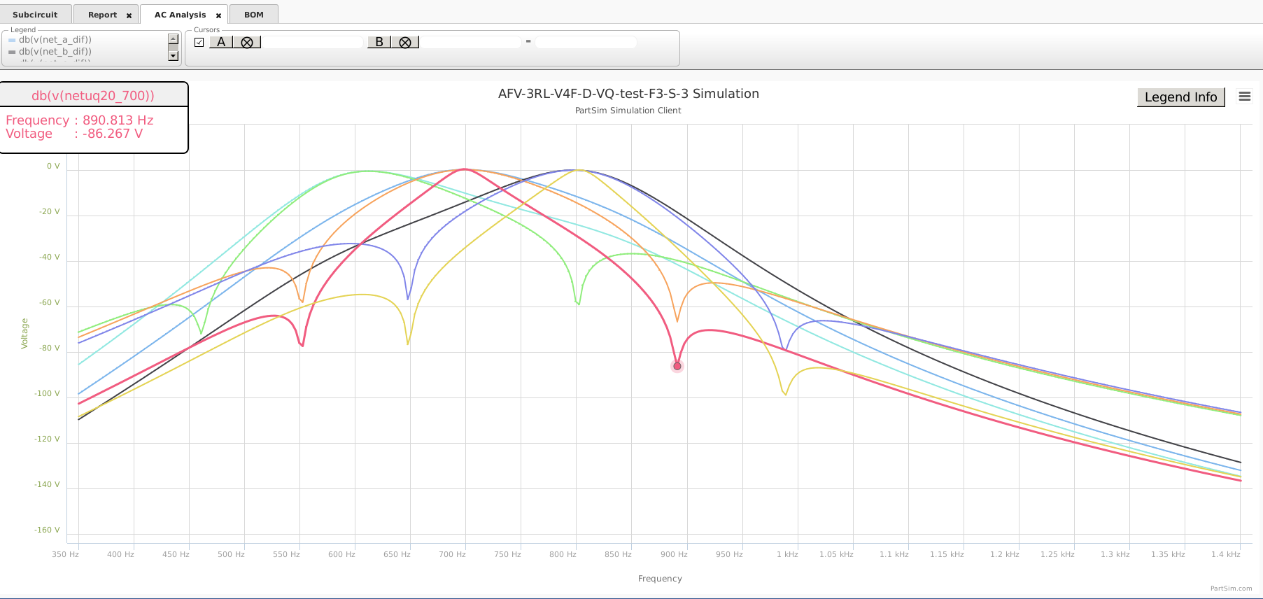
************************************************************************************
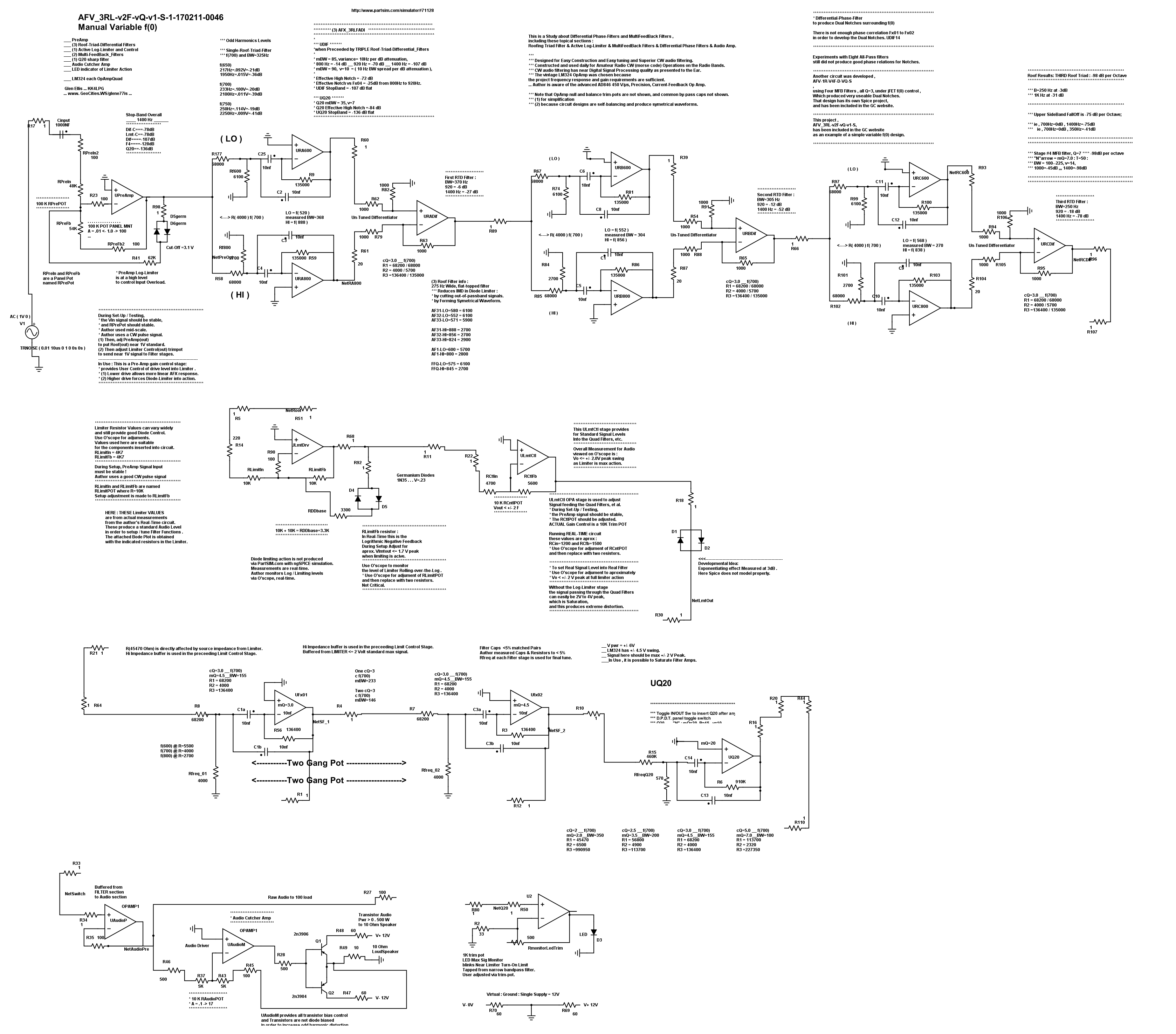
The below 'test circuit' and plots are NOT spectacular
but were given a fair test.
... Goal was to test use of only Two MFB filters .
... Dual Notches could not be well developed when using only Two MFB filters.
... More phase alignment is required to generate the Dual Notches.
... Therefore, No notches are presented in the below plots.
... Adjustable in real-time from 600Hz continuous to 800Hz
by a single front-panel mounted 5K Pot for User Real-Time Control. 
*** AFV_3RL-v2F-vQ-v1-S design :
*** (1) with Three Roof Filters
*** (2) with only Two MFB filter stages
*** (3) with R(freq) controlled by a Two-Gang Pot
***
*** Bode Plot shows good regular BW measurements -3dB to -12dB down. 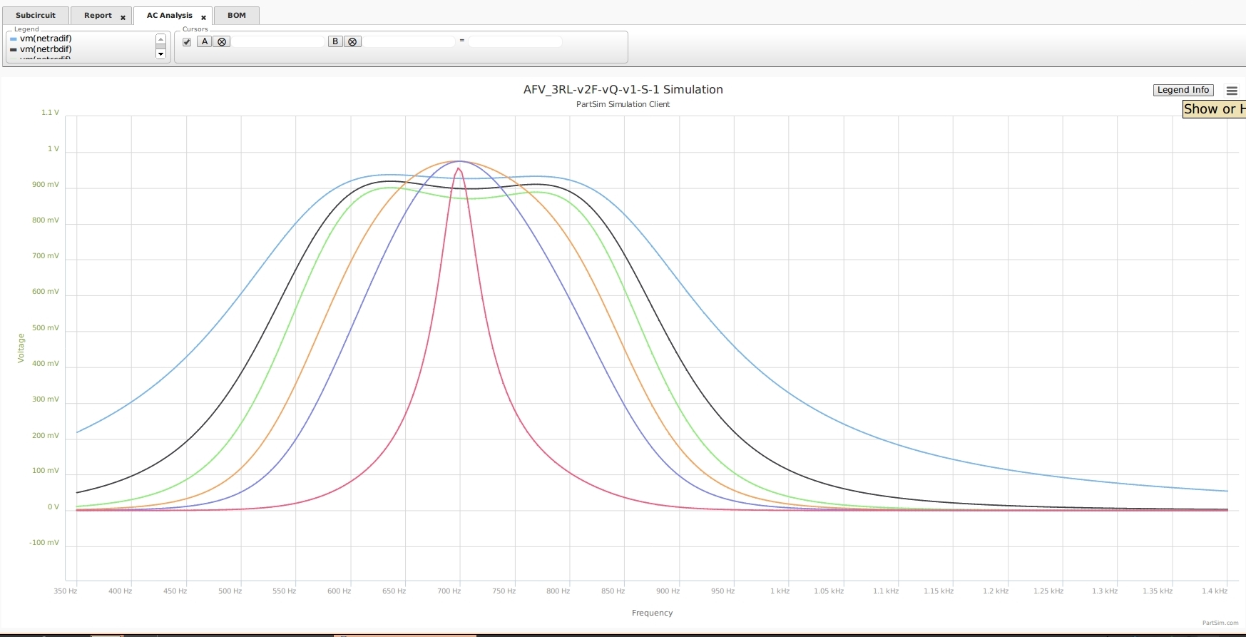
*** Magnitude Plot shows reasonable bottom end attenuation ... Plus / Minus Octave.
*** Q20 (red) is the sharp bandpass.
*** Phase Alignment is not sufficient to produce Dual-Notch. 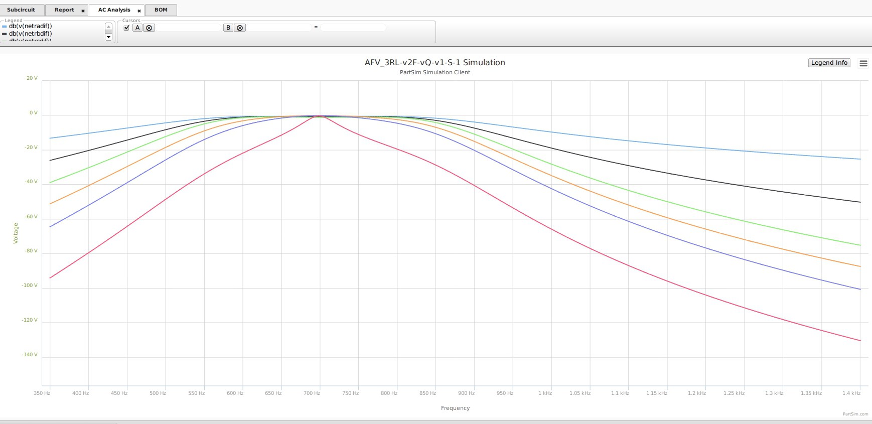
**************************************************************************