
GC_ET_AFX_CW_Filter.html
2021-07-18 11:20:01
( Be sure to Refresh your pages, each visit, as web-site construction has been ongoing since 1995, for 25 years
( ...... and may have changed since your last visit . Remember, the internet browser retains a cached page.


"AFX" filter circuit :
Differentiated & Integrated post-Filter Stages
& Q=20 stage
are detailed on a special page.
AFX : Analog CW Signal Processor.
***** 1. Preamp w limiter.
***** 2. Roofing Triad Filter,
***** 3. Active-Log_limiter,
***** 4. Quad MFB audio filter and Dual-Notches
***** 5. Audio out 0.5 W class-B.
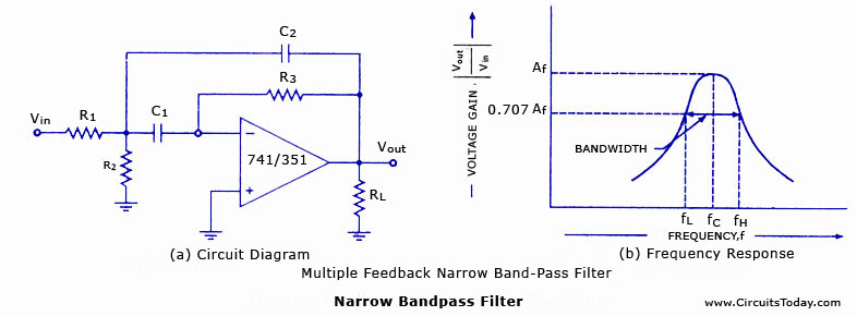
This Page is about the author's AFX core filter circuit for use with vintage and QRP rigs, such as the HW-8 .
*** Filter Topology Design notes :
*** Multi-FeedBack topology ( Deliyanis-Friend ) was chosen because :
*** (1) input vs output impedances match well when sequencing stages.
*** (2) single resistor frequency control for easy tuning to f() for sequenced filter stages .
*** (3) frequency adjustments alters gain by only the square-root of the f(change) .
*** (4) the Roof-Triad-Differential design is very tolerant of component variations ( and see note below ) .
*** (5) the Quad Filter components should be maintained exactly as shown
*** since they produce two phase related signals ( uFx01 and uFx04)
*** which drive the uDIF and uINT and uQ20 stages for the final results.
************************************************************************************************************
Note: in the following diagrams, Filter R2 is the R(freq) for adjusting f(center)
Note: the -1dB level is equivalent to 900 mV level and barely audible.
Note: the -3dB level is equivalent to 700 mV level the usual BandWidth point.
Note: [ (BW@-12dB - BW@-3dB ) / 9dB labeled as : "v" = slope of best fit for the Gaussian sideband shape ]
Note: All Filter and Differential stages are set to aprox. standard 1V peak
Note: Power Supply ByPass caps are not shown.
OpAmp Null trim pots were not used, in this development with LM-324 quad OpAmp chips.
************************************************************************************************************
*** First section is a Pre-Amp and Roof-Differential-Filter.
*** Second section is the Active-Limiter
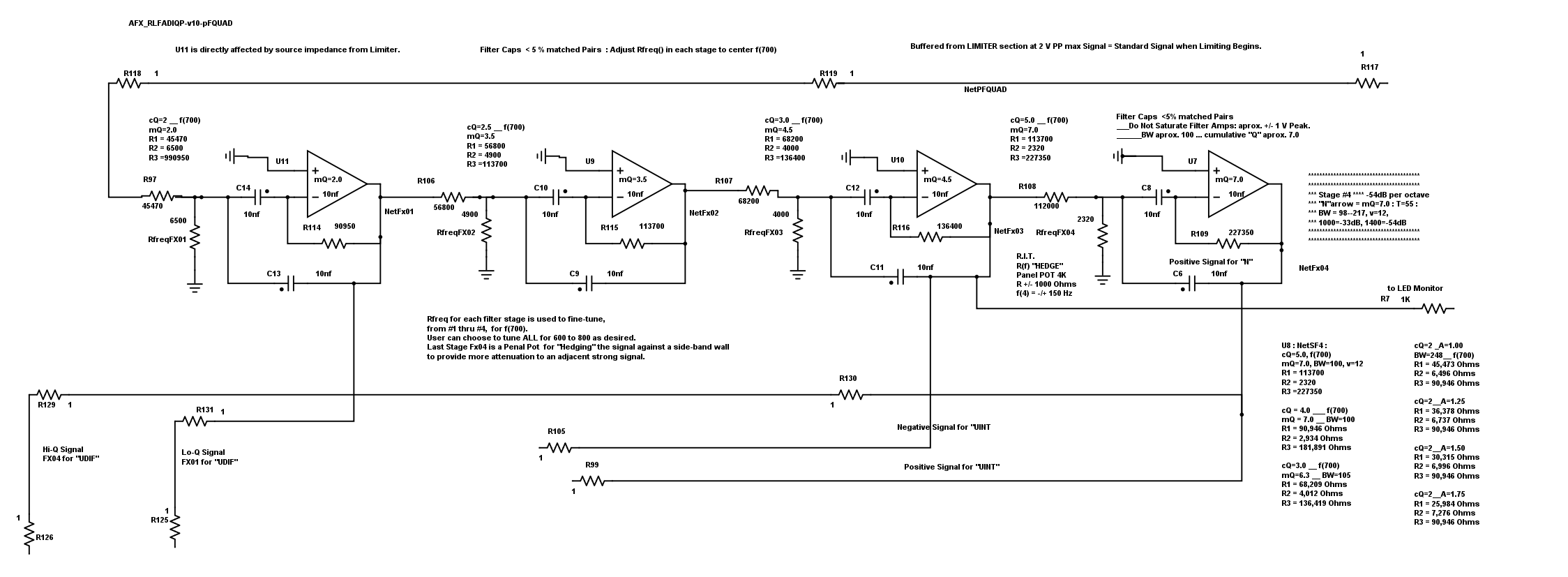
*** Third section is the Quad Stages MFB pass-band filter
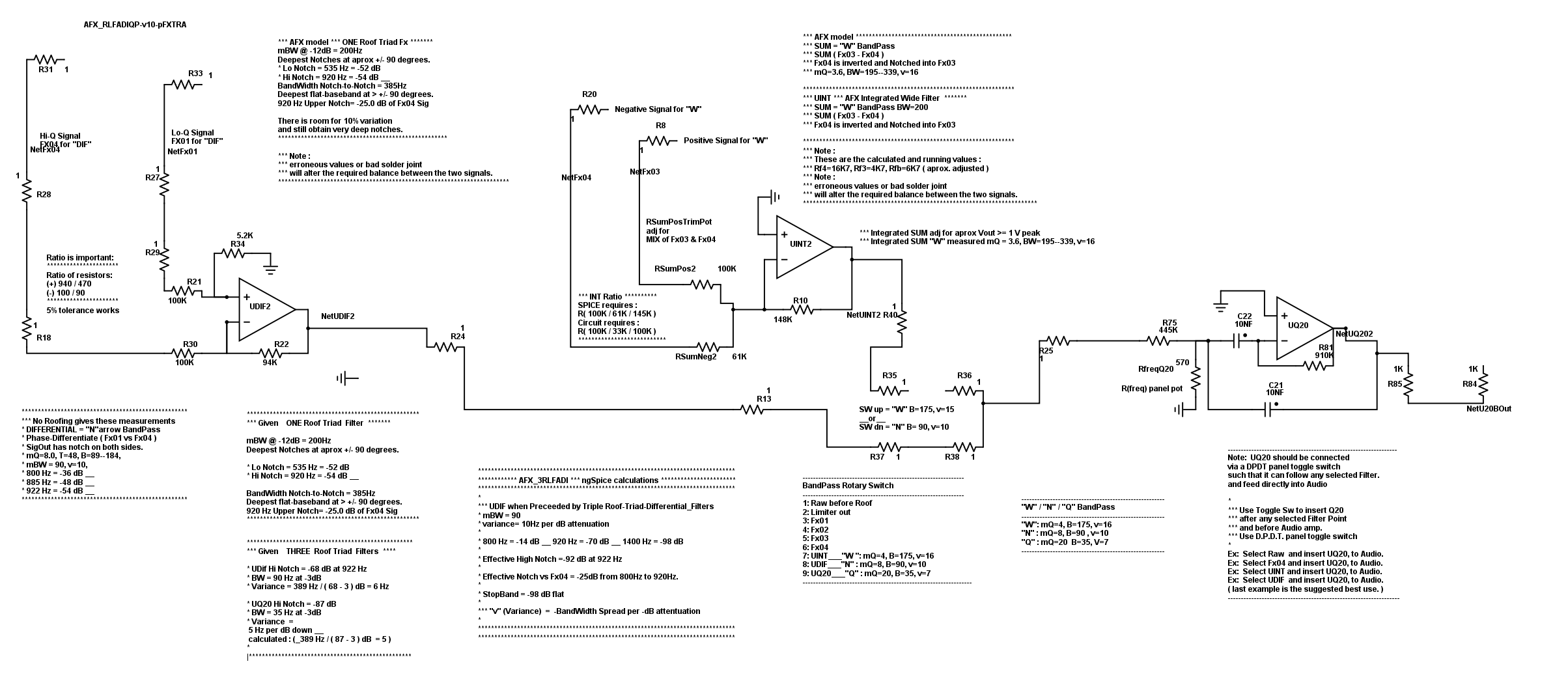
*** Fourth section contains the Differential and Integration "N"arrow / "W"ide stages
*** Fifth section is the Audio preamp and Class-B audio output.
*** Because all filter stages are set to a standard 1V peak,
the Filter-Select-Switch can tap most any stage for a signal into the Audio stage.
. That is the Basic AFX layout
*** Goal: "N"arrow and "W"ide passband signals.
********* Below is the section primarally about the Quad Filter
*** the reader should note these filter characteristics :
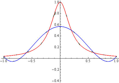
*** The DIFFerential and INTEgration Filter Stages have passband curves
*** that ARE NOT GAUSIAN CURVES.
GC_ET_AFX_CW_Filter.html
2021-07-18 10:54:30
( Be sure to Refresh your pages, each visit, as web-site construction has been ongoing since 1995, for 21 years
( ...... and may have changed since your last visit . Remember, the internet browser retains a cached page.


"AFX" filter circuit :
Differentiated & Integrated post-Filter Stages
& Q=20 stage
are detailed on a special page.
AFX : Analog CW Signal Processor.
***** 1. Preamp w limiter.
***** 2. Roofing Triad Filter,
***** 3. Active-Log_limiter,
***** 4. Quad MFB audio filter and Dual-Notches
***** 5. Audio out 0.5 W class-B.


This Page is about the author's AFX core filter circuit for use with vintage and QRP rigs, such as the HW-8 .
*** Filter Topology Design notes :
*** Multi-FeedBack topology ( Deliyanis-Friend ) was chosen because :
*** (1) input vs output impedances match well when sequencing stages.
*** (2) single resistor frequency control for easy tuning to f() for sequenced filter stages .
*** (3) frequency adjustments alters gain by only the square-root of the f(change) .
*** (4) the Roof-Triad-Differential design is very tolerant of component variations ( and see note below ) .
*** (5) the Quad Filter components should be maintained exactly as shown
*** since they produce two phase related signals ( uFx01 and uFx04)
*** which drive the uDIF and uINT and uQ20 stages for the final results.
************************************************************************************************************
Note: in the following diagrams, Filter R2 is the R(freq) for adjusting f(center)
Note: the -1dB level is equivalent to 900 mV level and barely audible.
Note: the -3dB level is equivalent to 700 mV level the usual BandWidth point.
Note: [ (BW@-12dB - BW@-3dB ) / 9dB labeled as : "v" = slope of best fit for the Gaussian sideband shape ]
Note: All Filter and Differential stages are set to aprox. standard 1V peak
Note: Power Supply ByPass caps are not shown.
OpAmp Null trim pots were not used, in this development with LM-324 quad OpAmp chips.
************************************************************************************************************
*** First section is a Pre-Amp and Roof-Differential-Filter.
*** Second section is the Active-Limiter
*** Third section is the Quad Stages MFB pass-band filter
*** Fourth section contains the Differential and Integration "N"arrow / "W"ide stages
*** Fifth section is the Audio preamp and Class-B audio output.
*** Because all filter stages are set to a standard 1V peak,
the Filter-Select-Switch can tap most any stage for a signal into the Audio stage.
That is the Basic AFX modular layout
Our Advanced designs ( in later sections ) begin with the Roofing Filters.
********* Below is the section primarally about the Quad Filter
*** the reader should note these filter characteristics :
*** The DIFFerential and INTEgration Filter Stages have passband curves
*** that ARE NOT GAUSIAN CURVES.

********************************************************************************************
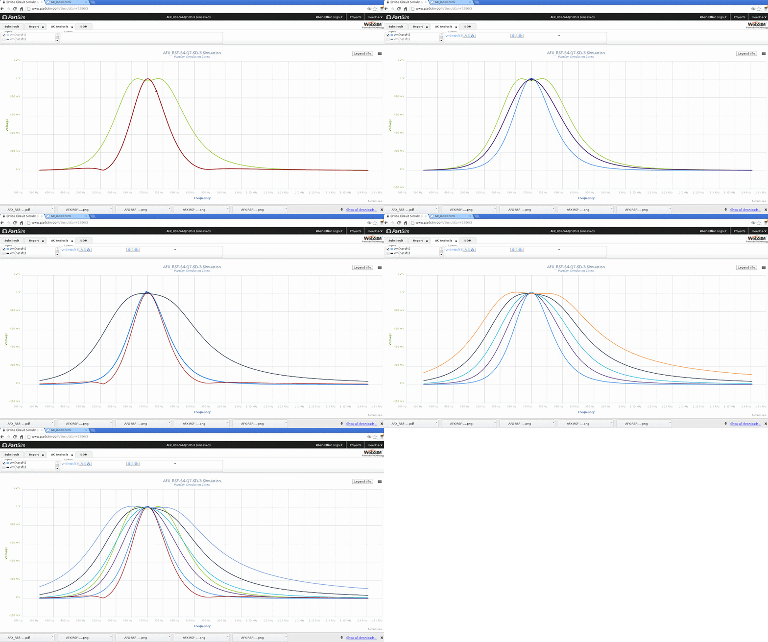
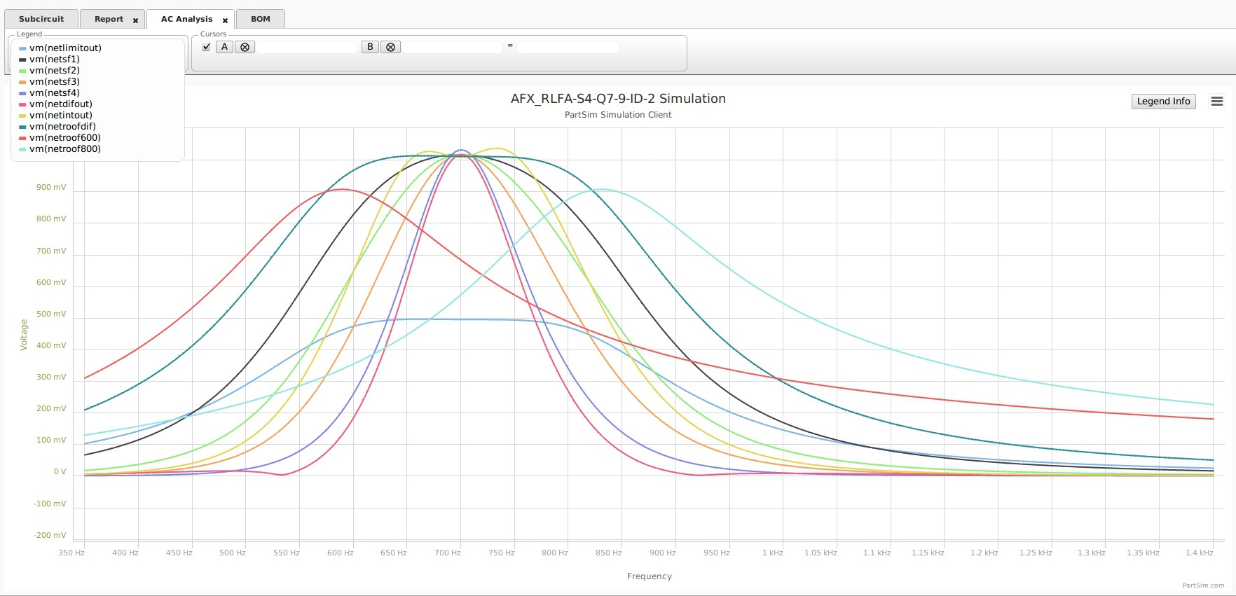
*** Below is Bode for All Waveforms and INTEgration "W" and DIFFerential "N"
*** "W"ide is flat topped in yellow.
*** "N"arrow is double Notched in red.
Here: Narrow Differential signal is RED and Wide Integration signal is YELLOW.
*** Special Note : ***********************************
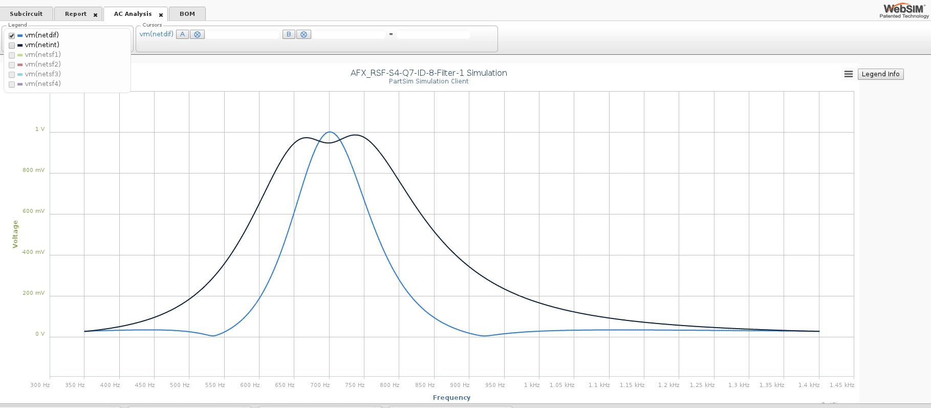
*** F1-F4_DIF = Notches are -25dB below Fx04
*** DIF :
*** BW=86--190___v=12
*** Notch at 533 @ -50dB
*** Notch at 920 @ -50dB
*** StopBand= -48dB to limits
******************************************************
*** F3+F4_INT
*** BW=176--369___v=-22
*** StopBand = -19dB to -42dB
**************************************
*** Graphical Concept for the Dual-Notches
*** The DIF stage produces a "N"arrow signal, with dual notches surrounding 700Hz
*** Graphical Concept for the Dual-Notches 
*** Where the wave-forms cross, there is zero difference in amplitude,
*** and a Differential OPA can produce a Notch at each cross-over !!!
********************************************************************************************
Below: Narrow Differential signal is RED and Wide Integration signal is BLUE![]()
***************************************************************************************
*** Below :
*** Bode for Fx01 (black), Fx04 (blue), and the Dif "N" (red) .
*** At 930Hz , the Dif "N" (red) versus Fx04 (blue) is -25 dB.
*** This is a log scale plot so the plots appear closer than reality. 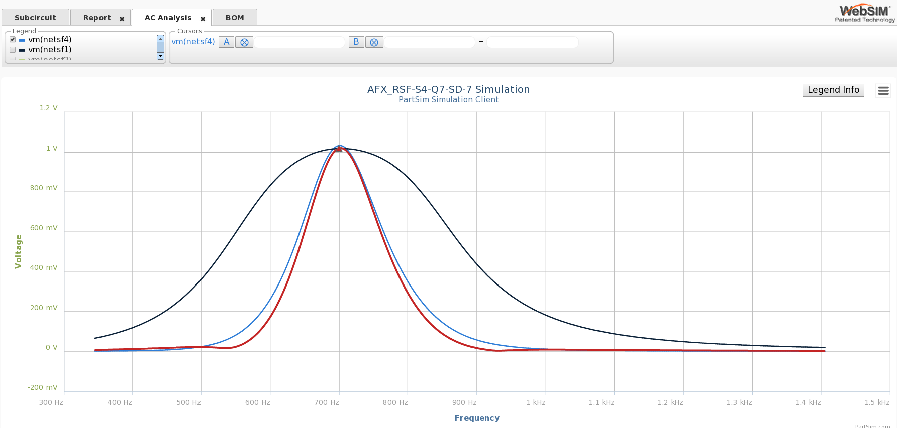
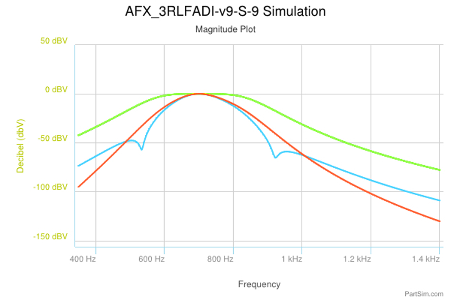
*** Below is a "Magnitude Plot" which emphasizes the dB relations.
**************************************************************************************************************
*** More Discussion about the Standard "AFX-RSF" Circuit
1) Bullet-Proof Construction and Easy to tune just using a VOM and ordinary signal source off the air.
2) Very steep skirts .
3) very low passband signal level at 1000 Hz .
*** PreAmp has wide gain.
*** Roofing Filter is very wide.
*** Log Diode Limiter is a single stage, instant response, Actively Driven by user control.
*** LED indicator for Limiter-in-Action ( and if tapped from Fx04, then indicates also the Center-of-Passband).
*** Filter stage BandWidth Ranges : "W"ide Q=2.5 BW=250, "N"arrow Q=5 BW=100. ... Measured "Q" are 3.5 and 6.5
*** Quad Filter has Variable f(0) in Stage #4 which acts like an RIT tuner for +/- 75 Hz.
*** Hedge f(0) by shifting the Stage #4 f(0) within the source passband, to better capture a slightly QSY signal.
*** Optional :
* extra is a Stage UDIF ( DIFferentiating Fx01 with Fx04 ) to produce a "N"arrow Double-Notched signal.
* extra is a Stage UINT ( INTegrating #3 negative and #4 positive signals ) to produce a "W"ide flat-top steep sided signal.
* Note: the Calculated "cQ" and Measured "mQ" are shown.
* Because circuit measurements show the cumulative effect of several stages.
* the Measured "mQ" is always much higher than the Calculated "cQ".
* The Cumulative Measured "mQ" is the Real-Time Signal out of this filter.
::: Some Circuit specs:
::: 12V split supply. So, +/- 6V supply
::: LM741 & LM308 Vout max = +/- 4.2V. ::: LM324 Vout max = +/- 5.2V
General Setup :
::: Set Diode Limiting at 1.25 V as Limit Function begins. Variance is OK.
::: Set Limiter Vout = +/- 1.0V peak into audio filters , as a Standard Signal Level.
::: Filters run at +/- 1V peak aprox. max. analogous to the Log-Limiter Peak range.
::: Filter Stage #4, calculated cQ=5, ,measured mQ=7 cumulative, measured BW=100.
Hedging control ( Discussed in the R.I.T. section ) :
:::: Here, R(freq) is adjusted +/- 1KOhm to vary f() 100Hz, aprox. 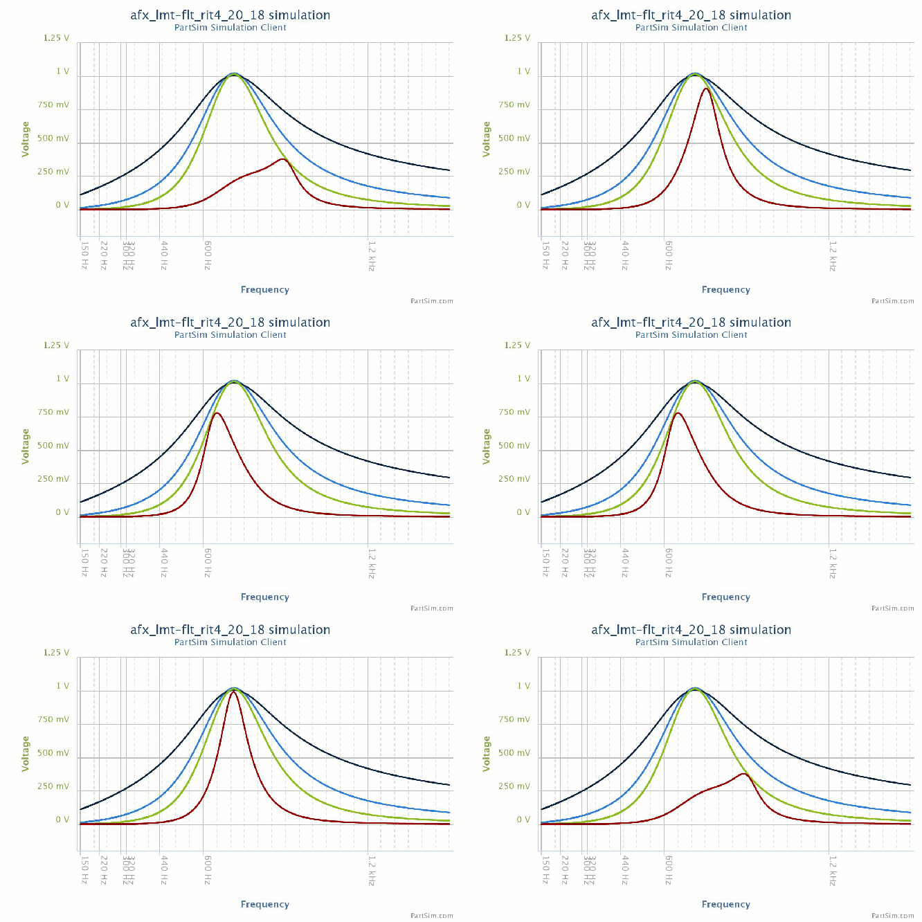
(( this will vary when combined with Differentiation and Integrating circuits ))
( author uses a Panel Pot for hand control.)
( Is used as a Hedging control to push BandPass Peak Freq against the BandPass Skirt wall. )
( The net effect is to push unwanted signals down the opposite BandPass Skirt. )
***********************************************************************************************************
#1 , #2, #3, #4 filter stages are standard MFB topology and Produce a standard Gausian BandPass.
Underlapping ( by increasing "Q" in succeding stages ) reduces cumulative GroupDelay distortion.
Measurements at #4 Vout:
Measured Q = 7.0 (cumulative effective “Q”).
BW=90,130,165,200 @ -3,-6,-9,-12 db.
Var=12 Hz passband spread per dB attenuation ,
Fx4 Floor=-41dB at 1000 Hz.
#5 and #6 stages are the Differential and Integral stages.
These are untuned stages, and produce a very Non-Gausian BandPass.
****************************************************************************************
See the Differentiated & Integrated post-Filter Stages for details.
*** #5 UDIF NARROW 100Hz BW DIFFerential stage
*** where Filter#4 (mQ=7.0) is inverted and subtracted from Filter#1 (mQ=2.0)
*** easily producing dual -48 dB notches at aprox. +/- 200 Hz:
*** StopBand is aprox. -45 dB to limits.
*************************************************************************************************
See the Differentiated & Integrated post-Filter Stages for details.
WIDE: #6 UINT stage is a INTegration of Fx#3 positive and Fx#4 negative.
INT stage produces Very Broad Top of 175 Hz.
INT stage produces a sideband skirt steeper than the sources.
Final INTegrated stage "W"ide ------------ mQ=4, BW=175, v=16, K=-24

That is the author's AFX core filter circuit with the Best-of-Class development in the "AFV" circuit.
The projectt is for use with Vintage and Analog QRP rigs, such as the Heathkit HW-8
It also provides excellent results attached to a Kenwood 830-S.
*************************************************************************************************************************


********************************************************************************************
*** Below is Bode for All Waveforms and INTEgration "W" and DIFFerential "N"
*** "W"ide is flat topped in yellow.
*** "N"arrow is double Notched in red.
Here: Narrow Differential signal is RED and Wide Integration signal is YELLOW.

*** Special Note : ***********************************
*** F1-F4_DIF = Notches are -25dB below Fx04
*** DIF :
*** BW=86--190___v=12
*** Notch at 533 @ -50dB
*** Notch at 920 @ -50dB
*** StopBand= -48dB to limits
******************************************************
*** F3+F4_INT
*** BW=176--369___v=-22
*** StopBand = -19dB to -42dB
**************************************
*** Graphical Concept for the Dual-Notches
*** The DIF stage produces a "N"arrow signal, with dual notches surrounding 700Hz
*** Graphical Concept for the Dual-Notches 
*** Where the wave-forms cross, there is zero difference in amplitude,
*** and a Differential OPA can produce a Notch at each cross-over !!!
********************************************************************************************
Below: Narrow Differential signal is RED and Wide Integration signal is BLUE![]()
***************************************************************************************
*** Below :
*** Bode for Fx01 (black), Fx04 (blue), and the Dif "N" (red) .
*** At 930Hz , the Dif "N" (red) versus Fx04 (blue) is -25 dB.
*** This is a log scale plot so the plots appear closer than reality. 
*** Below is a "Magnitude Plot" which emphasizes the dB relations.

**************************************************************************************************************
*** More Discussion about the Standard "AFX-RSF" Circuit
1) Bullet-Proof Construction and Easy to tune just using a VOM and ordinary signal source off the air.
2) Very steep skirts .
3) very low passband signal level at 1000 Hz .
*** PreAmp has wide gain.
*** Roofing Filter is very wide.
*** Log Diode Limiter is a single stage, instant response, Actively Driven by user control.
*** LED indicator for Limiter-in-Action ( and if tapped from Fx04, then indicates also the Center-of-Passband).
*** Filter stage BandWidth Ranges : "W"ide Q=2.5 BW=250, "N"arrow Q=5 BW=100. ... Measured "Q" are 3.5 and 6.5
*** Quad Filter has Variable f(0) in Stage #4 which acts like an RIT tuner for +/- 75 Hz.
*** Hedge f(0) by shifting the Stage #4 f(0) within the source passband, to better capture a slightly QSY signal.
*** Optional :
* extra is a Stage UDIF ( DIFferentiating Fx01 with Fx04 ) to produce a "N"arrow Double-Notched signal.
* extra is a Stage UINT ( INTegrating #3 negative and #4 positive signals ) to produce a "W"ide flat-top steep sided signal.
* Note: the Calculated "cQ" and Measured "mQ" are shown.
* Because circuit measurements show the cumulative effect of several stages.
* the Measured "mQ" is always much higher than the Calculated "cQ".
* The Cumulative Measured "mQ" is the Real-Time Signal out of this filter.
::: Some Circuit specs:
::: 12V split supply. So, +/- 6V supply
::: LM741 & LM308 Vout max = +/- 4.2V. ::: LM324 Vout max = +/- 5.2V
General Setup :
::: Set Diode Limiting at 1.25 V as Limit Function begins. Variance is OK.
::: Set Limiter Vout = +/- 1.0V peak into audio filters , as a Standard Signal Level.
::: Filters run at +/- 1V peak aprox. max. analogous to the Log-Limiter Peak range.
::: Filter Stage #4, calculated cQ=5, ,measured mQ=7 cumulative, measured BW=100.
Hedging control ( Discussed in the R.I.T. section ) :
:::: Here, R(freq) is adjusted +/- 1KOhm to vary f() 100Hz, aprox. 
(( this will vary when combined with Differentiation and Integrating circuits ))
( author uses a Panel Pot for hand control.)
( Is used as a Hedging control to push BandPass Peak Freq against the BandPass Skirt wall. )
( The net effect is to push unwanted signals down the opposite BandPass Skirt. )
***********************************************************************************************************
#1 , #2, #3, #4 filter stages are standard MFB topology and Produce a standard Gausian BandPass.
Underlapping ( by increasing "Q" in succeding stages ) reduces cumulative GroupDelay distortion.
Measurements at #4 Vout:
Measured Q = 7.0 (cumulative effective “Q”).
BW=90,130,165,200 @ -3,-6,-9,-12 db.
Var=12 Hz passband spread per dB attenuation ,
Fx4 Floor=-41dB at 1000 Hz.
#5 and #6 stages are the Differential and Integral stages.
These are untuned stages, and produce a very Non-Gausian BandPass.
****************************************************************************************
See the Differentiated & Integrated post-Filter Stages for details.
*** #5 UDIF NARROW 100Hz BW DIFFerential stage
*** where Filter#4 (mQ=7.0) is inverted and subtracted from Filter#1 (mQ=2.0)
*** easily producing dual -48 dB notches at aprox. +/- 200 Hz:
*** StopBand is aprox. -45 dB to limits.
*************************************************************************************************
See the Differentiated & Integrated post-Filter Stages for details.
WIDE: #6 UINT stage is a INTegration of Fx#3 positive and Fx#4 negative.
INT stage produces Very Broad Top of 175 Hz.
INT stage produces a sideband skirt steeper than the sources.
Final INTegrated stage "W"ide ------------ mQ=4, BW=175, v=16, K=-24


That is the author's AFX core filter circuit with the Best-of-Class development in the "AFV" circuit.
The projectt is for use with Vintage and Analog QRP rigs, such as the Heathkit HW-8
It also provides excellent results attached to a Kenwood 830-S.
*************************************************************************************************************************