2021-01-06 11:31:45
GC_ET_PFB.html
2021-01-06 11:31:45
VŠB-Technical University of Ostrava, · Department of Electrical Engineering
__Original Design for Positive-FeedBack BandPass Filter. ( GC_ET_PFB-rg.html )
2018-01-10
11:08:01
Based on circuit design by Dr. Josef Punchochar
Copy from Josef Punchochar article :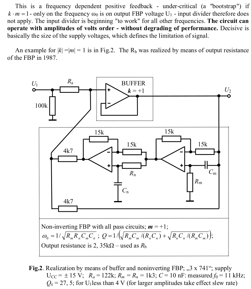
Developed into this by Glen Ellis :
Example of circuit modification to handle Positive Boot-Strap Feedback via Multiple-Feedback Band Pass Filter.
Advantage is : Adjust f(0) via a single resistor R(freqAdj) +/- 300 Hz.
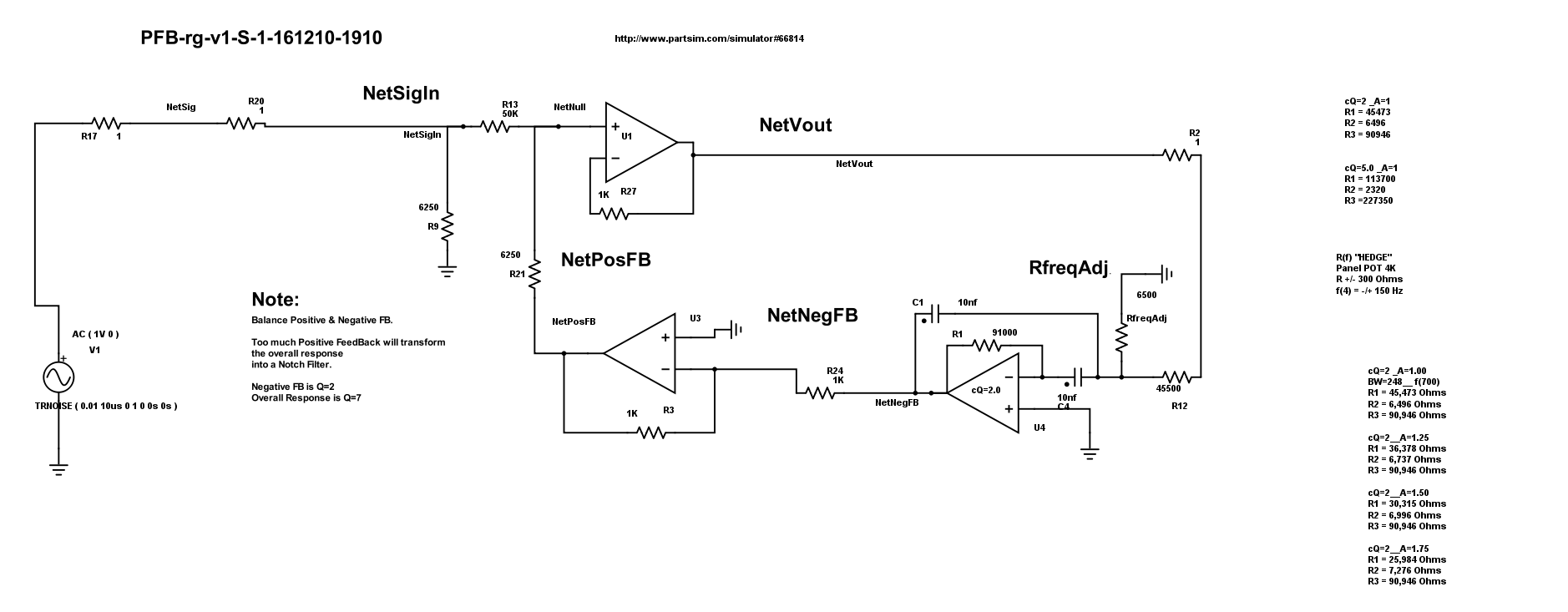
SPICE circuit, 161210, Glen Ellis.
Based on circuit design by Josef Punchochar, Research Gate Net
Example of circuit modification to handle Positive Boot-Strap Feedback via Multiple-Feedback Band Pass Filter.
Advantage : Adjust f(0) via a single resistor R(freqAdj) +/- 300 Hz.
Balance between Positive & Negative FB
Too much FeedBack will transform circuit into a Notch Filter.
V(out) is NetVout
f(0) = 700 Hz
FeedBack Q=2
Effecive Q=7
BW=100 Hz
Original NetSigIn ( source signal ) is flat ( green ).
FeedBack inverted ( black ) (generated at Q=2)
Overall Response is Q=7 Positive BandPass ( blue ). 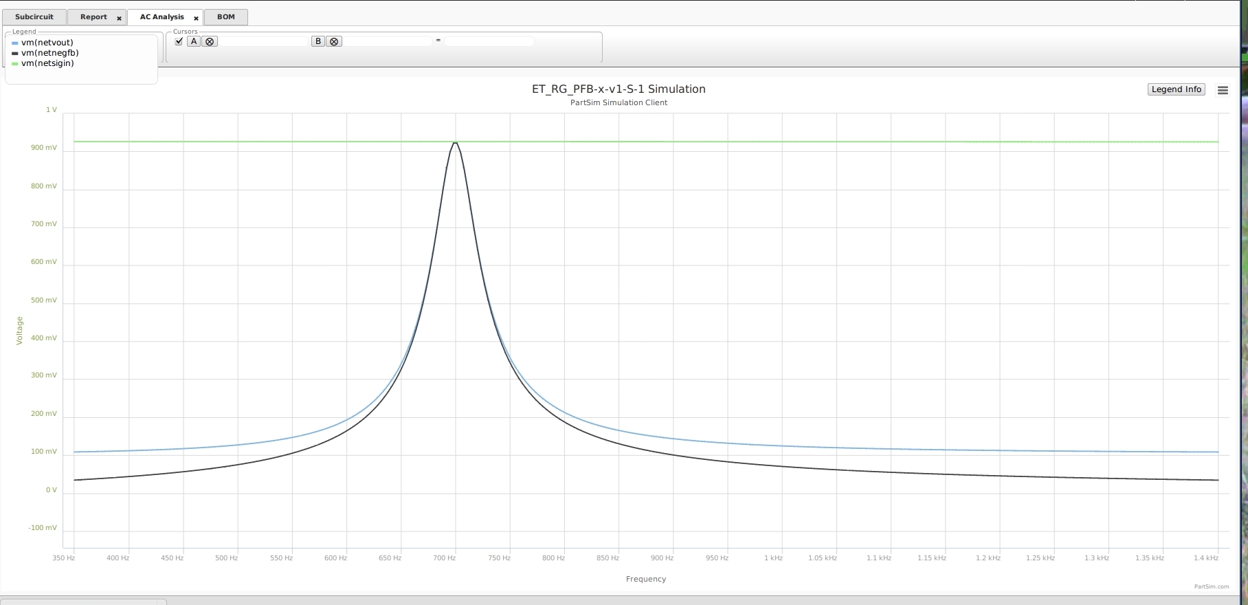
Transient Plot 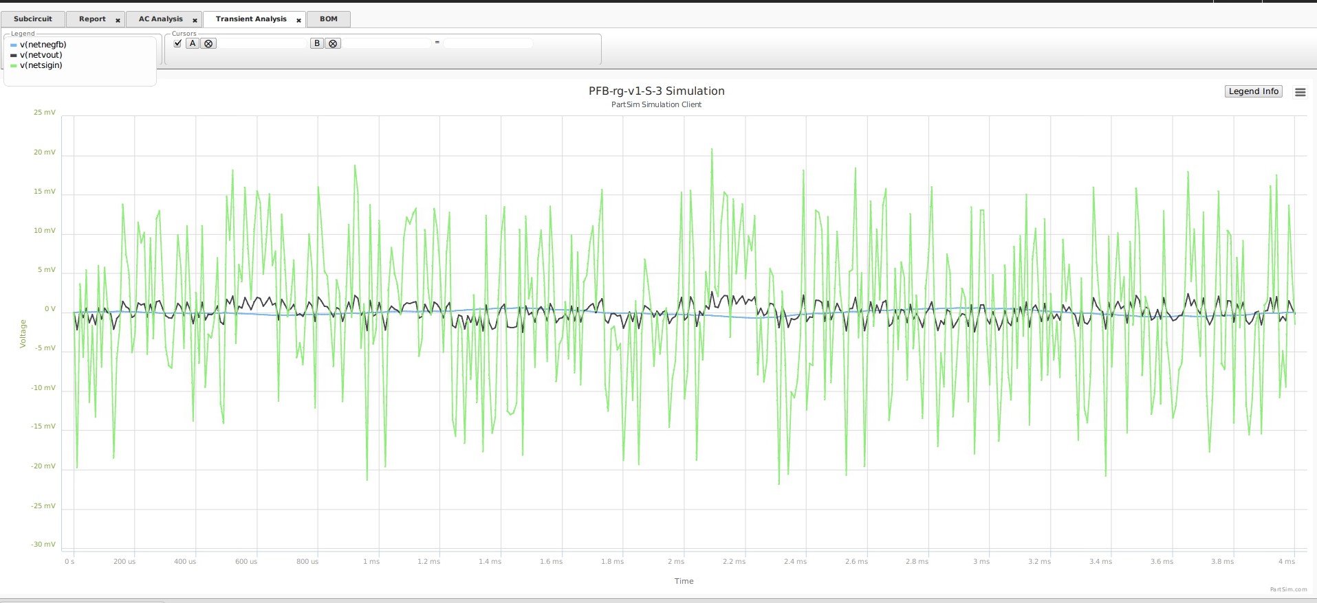
Adjust f(0) via a Single Resistor R(freqAdj) +/- 300 Hz.
Change f(0) via R6 .
Initially R(freq) is 6500 Ohm. Adjust : Up = lower f(0) and Down = higher f(0).
In f(0) change,
Gain will change as the minor ratio of R(in) / R(freq).
Q will change as squareroot of delta(f) change.
But BW will remain same.
( Author uses this method for adjusting f(0) change of +/- 300 Hz. )
*** Demonstrating shifting f(0) via R(freqAdj)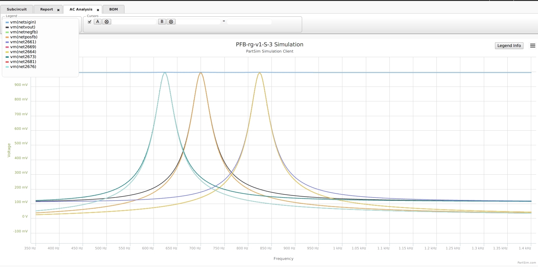
*** Demonstrating circuit to generate bode of shifting f(0) via R(freqAdj)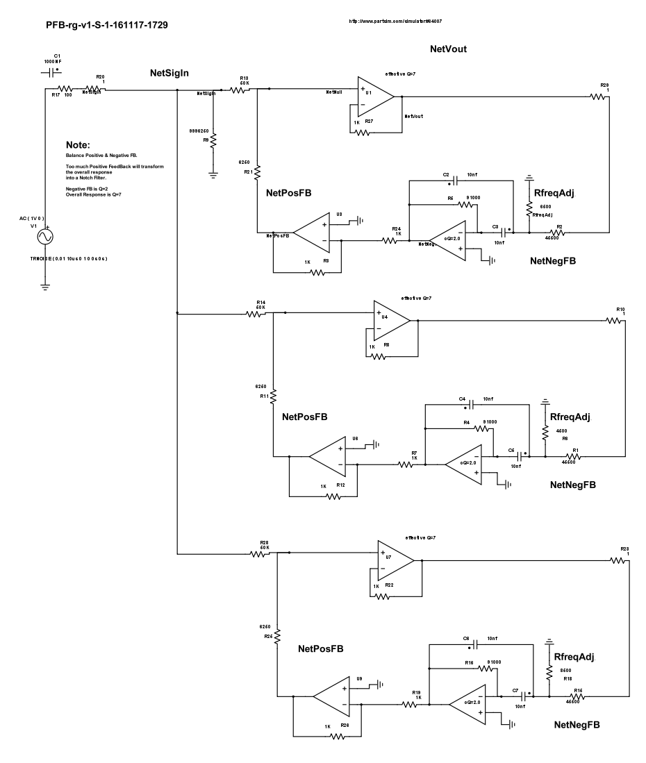
*********************************************************************************************
Further Reading on Positive Feed-Back developments :
AAA GC_ET_PFB-bpf.html
GC_ET_PFB-bpf.html
2018-01-10
11:05:01
*** Based on circuit design by Dr. Josef Punchochar , Research Gate Net
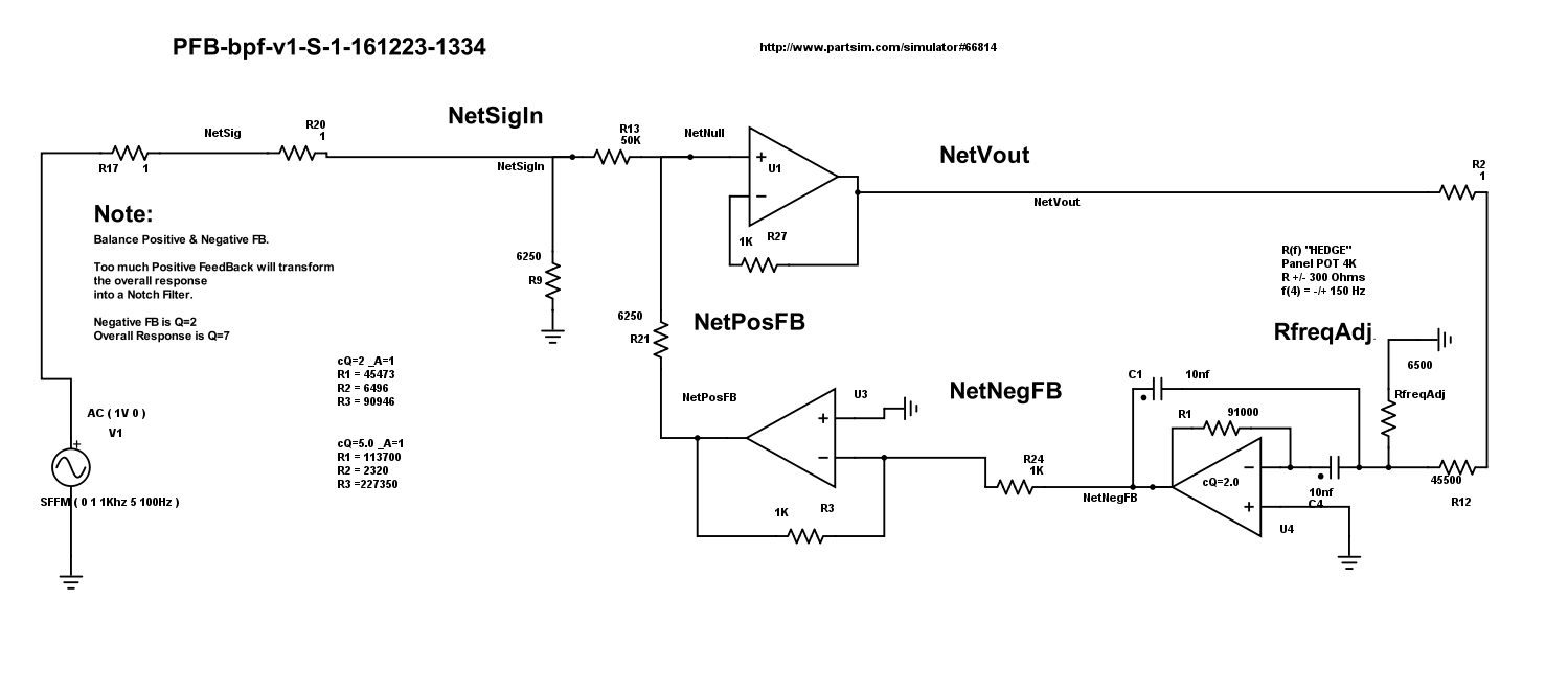
*** the Positive-FeedBack Band-Pass Filter, with single resistor f() control.
Negative FeedBack is Q2 and PFB BandPass V(out) is Q7
Example of circuit modification to handle Positive Boot-Strap Feedback via Multiple-Feedback Band Pass Filter.
Advantage is : Adjust f(0) via a single resistor R(freqAdj) +/- 500 Hz.
*** SPICE circuit, Glen Ellis.
*** Example of circuit modification to handle Positive Boot-Strap Feedback via Multiple-Feedback Band Pass Filter.
*** Advantage : Adjust f(0) via a single resistor R(freqAdj) +/- 300 Hz.
*** Balance between Positive & Negative FB
*** else will transform circuit into a Notch Filter or into an Oscillator.
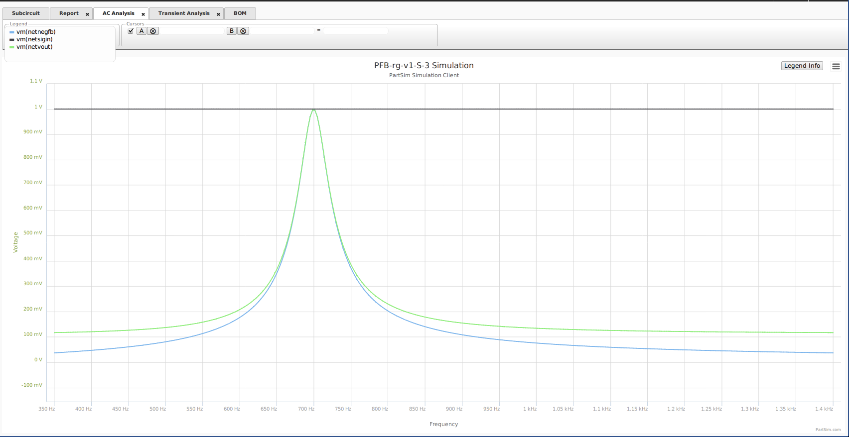
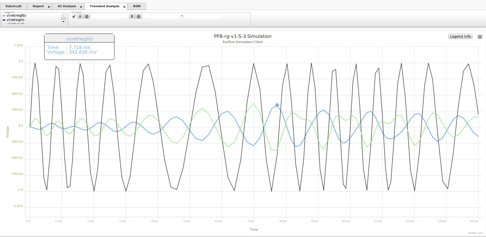
V(out) is NetVout
f(0) = 700 Hz
FeedBack Q=2
Effecive Q=7
BW=100 Hz
*** Original NetSigIn ( source signal ) is flat ( green ).
*** FeedBack inverted ( blue ) (generated at Q=7)
*** Overall Response is Q=7 Positive BandPass ( black ). 
Transient Plot : Noise Input and Positive-FeedBack and f(700) filtered V(out) . Green Noise, Black Positive-FeedBack, Blue f(700) V(out) . 
Adjust f(0) via a Single Resistor R(freqAdj) +/- 300 Hz.
Change f(0) via R6 [ R(freq) ].
Initially R(freq) is 6500 Ohm. Adjust : Up = lower f(0) and Down = higher f(0).
In f(0) change,
Gain will change as the minor ratio of R(in) / R(freq).
Q will change as squareroot of delta(f) change.
But BW will remain same.
( Author uses this method for adjusting f(0) change of +/- 300 Hz. )
*** Demonstrating shifting f(0) via R(freqAdj)
*** Demonstrating circuit to generate bode of shifting f(0) via R(freqAdj)
*********************************************************************************************
BBB GC_ET_PFB-osc.html
GC_ET_PFB-osc.html
2018-03-08
19:06:07
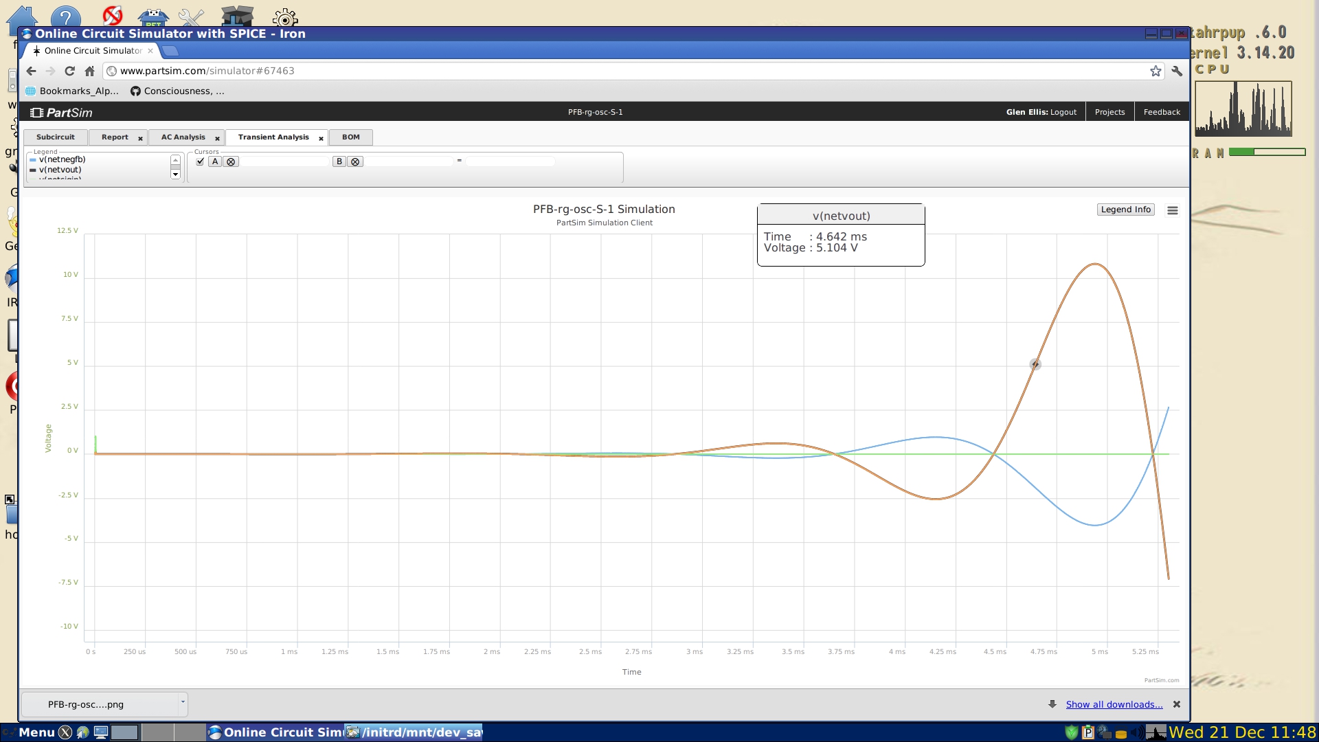
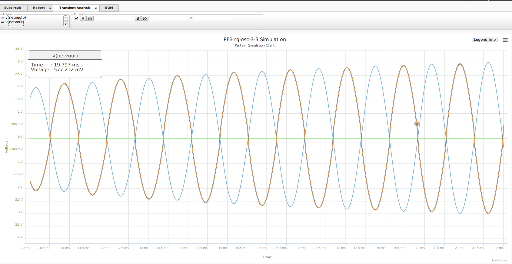
***** Our further development of the Positive Feed-Back Oscillator concept.
***** Positive Feed-Back with NO limiter control
***** produces a "SQUARE" V(out) , with single resistor f() control. 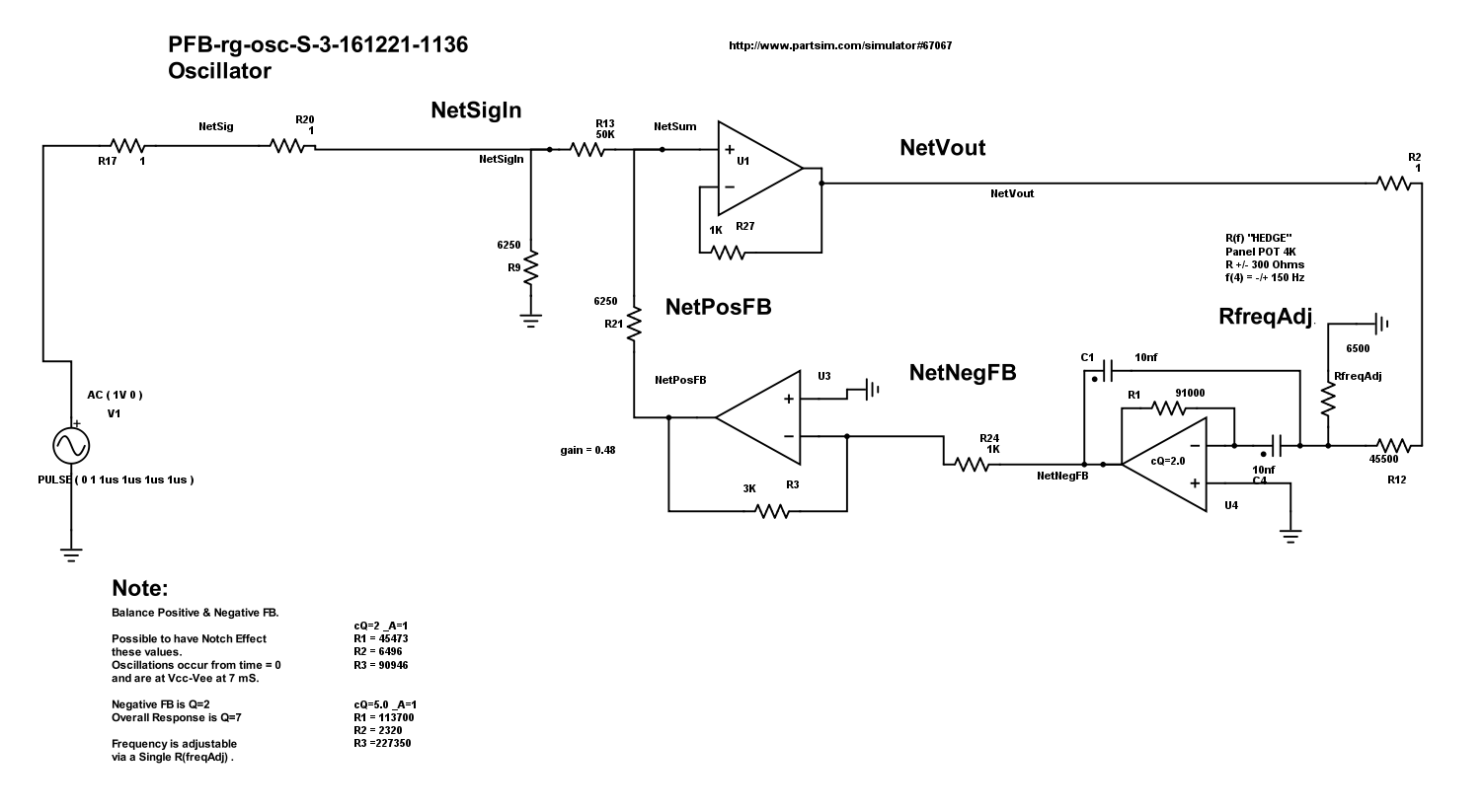
***** Positive Feed-Back with limiter control
***** produces a "SINE" V(out) , with single resistor f() control. 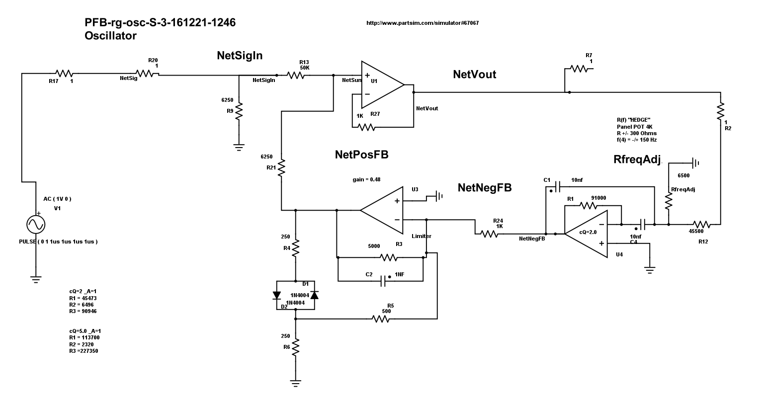
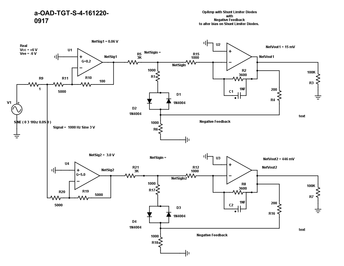
**************************************
*********************************************************************************************