******** Cutcher style Audio Circuit & LED drivers ************************************************
At this point, the previous filter stages have produced a 'soft' sine-shaped CW pulse .
All sub-harmonics and supra-harmoncs have been filtered out,
leaving principally a narrow filtered passband of 650 to 750 Hz.
What is needed is a "crisp" CW signal for better ear/brain function in reading the CW message.
High fidelity music audio is NOT desired. "Crisp" CW pulse is required.
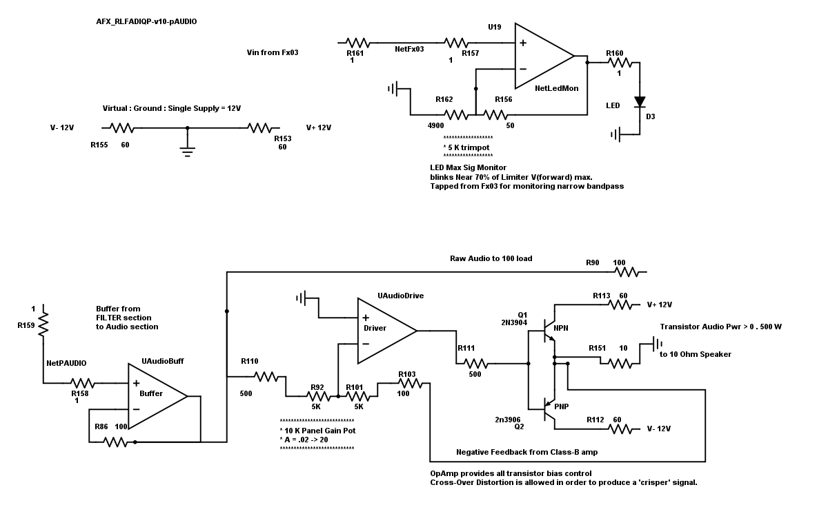
This stage is an OpAmp-Driven Two-Transistor Push-Pull Class "B".
OpAmp directly drives all Transistor Biasing, and produces cross-over distortion.
Our Design introduces third-harmonic distortion , inside this audio stage,
without saturating the amplifier, compressing the signal amplidude,
and loosing amplitude variations between the possible multiple signals in the passband.
In radio operations with CW, signals closer than 50Hz can occur and enter the passband.
Our goal is to produce a "crisper" CW audio for better ear/brain copy, without compression.
*** the Standard Audio Circuit schematic ( with simple LED monitor on top right )
OpAmp directly drives the Class-B audio stage,
Producing cross-over distortion.

**********************************************************************************************************************************************************************************
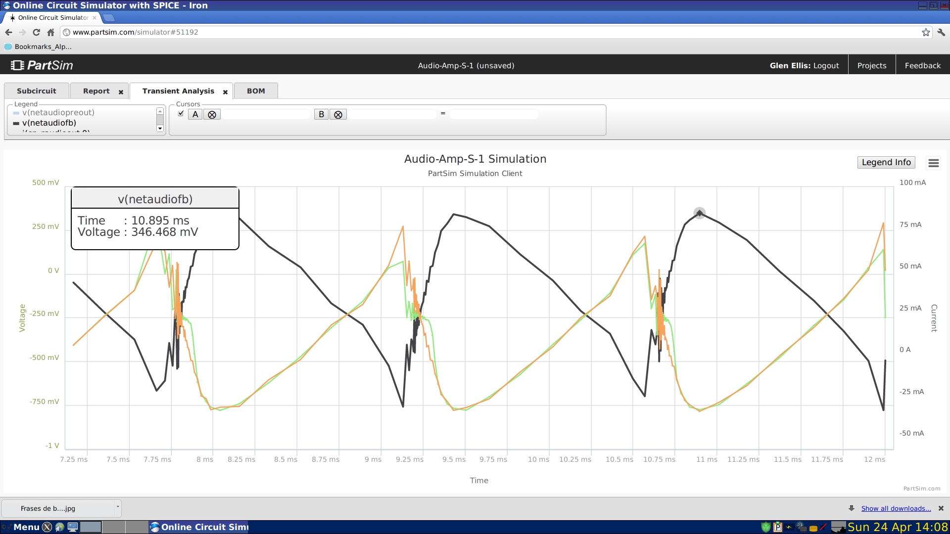
In the AFX circuit, the OpAmp Driven Two Transistor Push-Pull Class "B" produces a Saw-Tooth signal.
Received signal is a 'soft' sine-shaped CW pulse,
This stage produces a distorted Audio to the loud-speaker which is a sawtooth.
Design Goal of this un-biased class-B amp is to introduces third-harmonic distortion
to produce a "crisper" CW audio for better ear/brain copy.
The AFX produces an Audio V(out) resembling the below Transient Plot.
This Transient Plot shows the Distorted Audio Output which is a "crisper" signal to the ear.

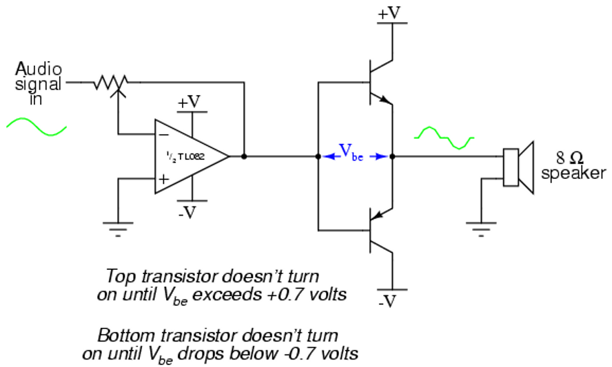
An Idealized circuit would be something like this :

source of this schem is unknown*** end ***
*********************************************************************************************************************************************************************
 Audio Stage
  Audio Stage

