
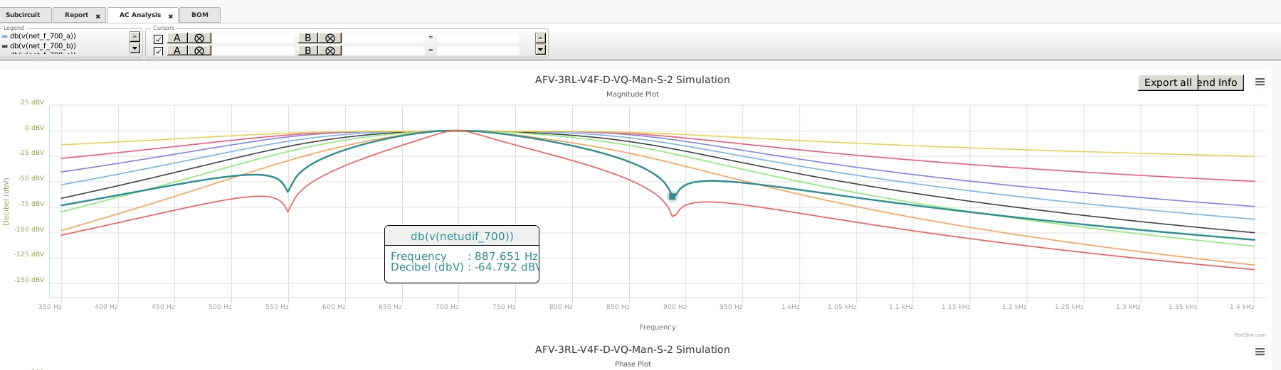
*** where the curves cross the amplitude difference is zero,
and the uDIF Differential Stage can produce Dual Notches .
Below is the "ANALOG" Magnitude Plot of the "AFX" filter .
GC_ET_AFX_CW_FiltRG.html
2020-12-30 19:32:05
2021-07-07 08:18:40
** (Home) ***
*** Graphical Concept for the "AFX" Phase-Filtered Dual-Notches ***
*** where the curves cross the amplitude difference is zero,
and the uDIF Differential Stage can produce Dual Notches .
Below is the "ANALOG" Magnitude Plot of the "AFX" filter .
Below is the
Excellent Digital Model and Documentation provided by
Dobromir Dobrev , Ph.D , Bulgarian Academy of Sciences
******************************************************************************************************
Excellent Digital Model has been provided by
Dobromir Dobrev ... Ph.D ... Bulgarian Academy of Sciences
This is a Digital Signal Process Development by by Dr. Dobrev.
This digital documentation was developed following discussion on ResearchGate.Net .
Developed using an entirely Digital Analysis of the AFX circuit concept.
It is remarkably close to the Analog Spice Results that the author obtained.
At the -48dB level, the digital results are the same as the analog development. 
Bode #1 shows Signal Input 532 Hz ( Low Notch )
vs. Band-Pass of odd harmonics from attenuated signal.
Bode #2 shows Signal Input 700 Hz
vs. tightly filtered PassBand Signal. 
Bode #3 shows Signal Input 923 Hz ( High Notch )
vs. Band-Pass of odd harmonics from attenuated signal.
Summary :
Bode #1 shows Signal Input 532 Hz vs. Band-Pass of odd harmonics from attenuated signal.
Bode #2 shows Signal Input 700 Hz vs. tightly filtered PassBand Signal.
Bode #3 shows Signal Input 923 Hz vs. Band-Pass of odd harmonics from attenuated signal.
******** (Home) *******************************************************************************************************************************************************