 |
|
|
|
|
|
|
|
|
|
|
|
|
|
|
|
|
|
|
|
|
|
|
|
|
|
|
|
|
|
|
|
|
|
|
|
|
|
|
|
|
| page 3 |
|
|
 |
|
|
|
| DYNO JET |
|
|
|
|
|
1 |
2 |
3 |
4 |
5 |
6 |
7 |
8 |
9 |
10 |
11 |
12 |
13 |
14 |
15 |
16 |
17 |
18 |
19 |
20 |
21 |
22 |
23 |
|
|
Page |
|
|
|
|
|
|
 |
|
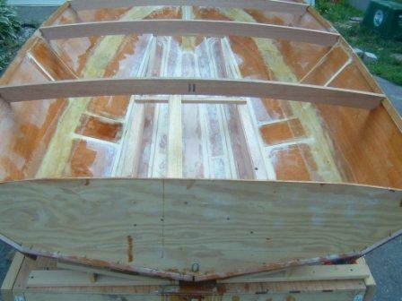
| You can see from this picture that the deck beams are installed - unfortunately the picture from the front is corrupted. If you look close you can see the longitudinals have been installed as well. |
|
|
|
|
|
 |
|
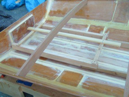
| Here is another view. You can see the transom board is filleted in. I should have waited to do this until after some of the other members were installed. Now I know for the next one - I can see my wife cringe.... |
|
|
|
|
|
 |
|
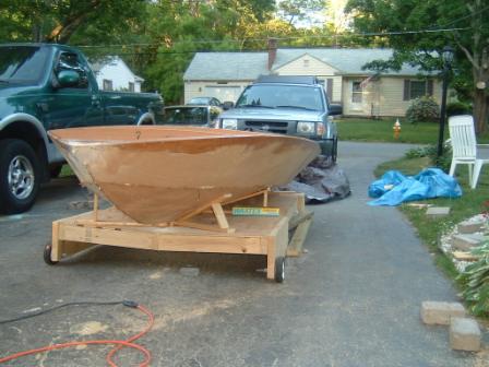
| Another picture from the front. It is amazing that at I am probably 100 hours into the project and it looks earily like some of the earlier pictures.... |
|
|
|
|
|
 |
|
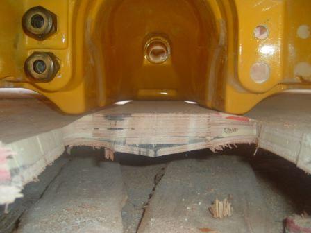
| Here we are starting to fit in the pump. Nothing is more painful than spending hours upon hours cutting, gluing and sanding, just to cut it out... I had intentionally left the last keel member out, so I could fit it over the jet ski pump..... |
|
|
|
|
|
|
 |
|
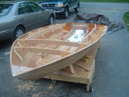
| Here is a great picture.... you can see what the inside will look like..... You can see the carlings have been installed - This was a huge relief because they are stiff members that take quite a bit to bend... |
|
|
|
|
|
|
Previous |
|
Next |
|