|
|
5
|
Editing Objects
|
|
In This Section:
|
|
|
|
|
|
Object Edit >
Align

|
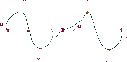
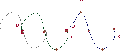
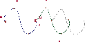
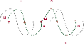
Aligning Curves and Surfaces
|
|
|
|
|
Purpose
Create positional, tangent, or curvature continuity between two curves or surfaces.
Overview
Using Align allows you to model with more freedom in the beginning, and still achieve strict continuity once the design is perfected.
The Align tool always creates positional continuity. Depending on the settings in the Align Control window, it can also create tangent and curvature continuity. After you align the objects, you can adjust the tangent magnitude where the two objects meet.
The Align tool works on the following combinations:
- another COS on the same surface
- curve on surface or trim edge
|
Tip:
|
The Align tool differs from Attaching Objects in that the
aligned objects remain separate. The Align tool also gives
you more control over how the objects are modified.
|
How To
To align two curves or surfaces:
|
|

|
-
1
-
Choose Align-
 from the Object Edit palette menu or double-click the Align tool icon. The Align Control window appears. from the Object Edit palette menu or double-click the Align tool icon. The Align Control window appears.
-
See Align Control window on page 88 for descriptions of the
options.
|
|
See Working With
Construction History on
page 46
|
-
2
-
Make sure Create History is checked.
-
You will almost always want construction history on. This
allows you to change the parameters or the geometry after
you exit the tool, and maintain the alignment. When you
are satisfied with the align, you can delete the history
information with Delete > Del constr history.
|
Tip:
|
To align two objects using the same settings as the last align,
you do not have to open the Align Control window. Just click
the Align tool.
|
-
3
-
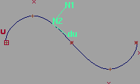
Pick the first curve, or an isoparm of the first surface.
-
Click as close as possible to the end of the curve or surface
where the two objects will meet.
-
4
-
Pick the second curve, or an isoparm of the second surface.
-
Click as close as possible to the end of the curve or surface
where the two objects will meet.
-
If the two surfaces already have positional continuity (that
is, their edges overlap), simply click in the same place you
did in step 3.
-
5
-
The Align tool creates the continuity specified in the Align Control window.
-
6
-
Use the controls in the Align Control window to interactively edit the alignment of the two objects.
To edit the construction history of aligned objects:
|
|
In the default color scheme,
objects with construction
history are drawn in green.
|
-
1
-
Pick two objects with alignment construction history in an edit window.
|
|

|
-
2
-
Click the Align tool.
-
The Align Control window opens with the settings of the
two objects.
-
3
-
Use the controls in the Align Control window to change the alignment of the objects.
To align two surfaces so that their edit points line up:
-
1
-
Create an initial curve.
-
2
-
Duplicate the curve to create the number of curves you need to build surfaces.
-
3
-
Reshape the curves using CVs. Do not move the edit points, as their parameter values must stay at the same percentages (ratios) on each copy of the curve.
-
4
-
Create your surfaces from the curves.
-
5
-
Use Align to align the surfaces.
To undo the alignment of two objects
- Choose Undo from the Edit menu.
-
This must be done immediately after using the Align tool,
before choosing another tool.
Tips and Notes
- You cannot manually edit CVs that are affected by align construction history. If you try to move them they will snap back into place.
- To preserve the tangent magnitudes at curve endpoints when you create positional continuity, use Move First, Move Second or Move Both. (See Position Menu below.)
- Align cannot modify curves on surface, trim edges, or interior isoparms. It can only modify free curves or surface edges. The exception to this rule is when aligning two curves on surface lying on the same surface.
- Align doesn't work on closed curves, and only works on closed surface if aligning along the free edges (for example, aligning the ends of two tubes).
- Turning on Skews Allowed, Align By Project, or setting Position to Explicit may cause tangent continuity to fail (see Align Control window on page 88). Aligning rational surfaces or aligning to a curve on surface could cause similar problems. Use the Continuity Check option to verify this (see page 95).
Align Control window
|
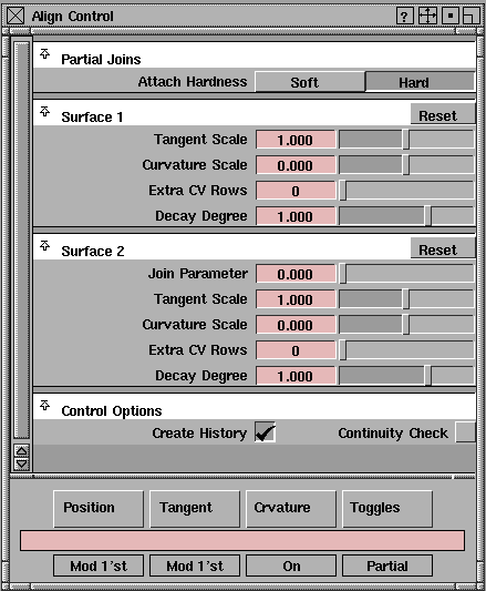
|
|
>
|
Note:
|
When aligning curves, the control window will contain less
parameters.
|
Position menu
|
|
|
Off
-
- Do not create positional continuity.
-
- You can use this setting in both the Position and Tangent menus to undo the alignment.
Explicit
-
- Keep the degree and number of spans of the surfaces the same during the alignment. Positional continuity is not enforced, so objects should already be positionally continuous when using this option.
-
- For curves, Explicit behaves the same as Off.
|
|
|
Modify First
-
- Change the shape of only the first object you selected to create positional continuity.
-
- For curves, Align moves the end CV of the first curve to the same position as the end CV of the second curve.
-
- For surfaces, Align moves the edge CVs of the first surface to the same positions as the edge CVs of the second surface.
|
|
|
Modify Second
-
- This option is similar to Modify First except that Align modifies only the second object you selected.
|
|
|
Modify Both
-
- Change the shape of both objects you selected to create positional continuity.
-
- For curves, Align moves the end CVs of the two curves to the halfway point between them.
-
- For surfaces, Align moves the edge CVs of the two surfaces to the halfway points between them.
|
|
|
Move First
-
- Move the entire first curve you selected, without changing the shape of the curve, so that its endpoint aligns with the endpoint of the second curve.
-
- If the first object you selected was a surface, it is first modified the same way as in Modify First, then all other CVs are translated an equal distance.
|
|
|
Move Second
-
- This option is similar to Move First except that Align moves only the second object you selected, without changing the shape of the curve.
-
- If the first object you selected was a surface, it is first modified the same way as in Modify Second, then all other CVs are translated an equal distance.
|
|
|
Move Both
-
- Move both curves you selected, without changing the shapes of the curves, so that the endpoints align at the halfway point.
Tangent Menu
|
|
|
Off
-
- Do not create tangent continuity.
-
- Use this setting in both the Position and Tangent menus to undo the alignment.
|
|
|
Modify First
-
- Modify the first object you selected to be tangent with the second object.
-
- For curves, the tangent vector passes through the CVs at the common endpoint and the next CV of the second curve. Align moves the next CV of the first curve to a point on the tangent vector such that the end tangent magnitude of the first curve is preserved.
-
- For surfaces, Align uses the same operation for each set of corresponding CVs along the common edge.
|
|
|
Modify Second
-
- This option is similar to Modify First except that Align modifies the second object to be tangent with the first object.
|
|
|
Free Intersection
-
- Modify the common endpoints or edges to create tangency.
-
- For curves, the tangent vector passes through the CVs next to the common endpoints on each curve. Align moves the common endpoints to the closest point on the tangent vector.
-
- For surfaces, Align uses the same operation for each set of corresponding CVs along the common edge.
|
|
|
Fixed Intersection
-
- Modify the objects to create tangency, while keeping the common endpoints or edges fixed.
-
- For curves, the tangent vector passes through the common endpoints, parallel to a line passing through the CVs next to the common endpoints on each curve. Align then moves these two CVs to points on the tangent vector such that the change to the end tangent magnitudes is minimized.
-
- For surfaces, Align uses the same operation for each set of corresponding CVs along the common edge.
Curvature Menu
Off
-
- Do not create curvature continuity.
|
|
|
On
-
- Modify the third-to-last CV of a curve or third-to-last row of CVs of a surface to match the curvature of the other object.
-
- If Tangent is Modify First, Free Intersection, or Fixed Intersection, Align modifies the first object to match the curvature of the second object.
-
- If Tangent is Modify Second, Align modifies the second object to match the curvature of the first object.
Toggles Menu
>
|
Note:
|
The Partial Joins, Align By Project, and Skews Allowed
options only apply when aligning surfaces.
|
|
|
|
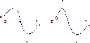
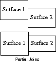
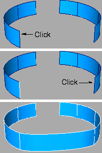
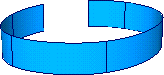
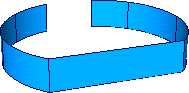
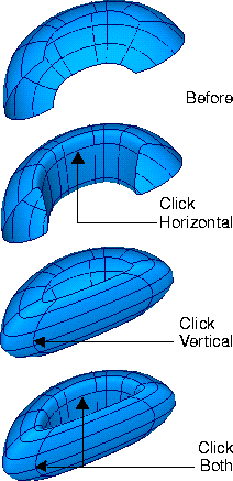
Partial Joins
-
- Allow surface edges to align only along their matching region. For example, the surfaces at left can be joined when this option is on.
-
- Turning this option on reveals the Attach Hardness control (see below).
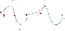
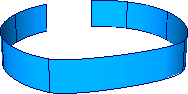
Skews Allowed
-
- Allow non-colinear (skewed) alignment of skewed surfaces.
-
- Turning this option on reveals the Skew 1 and Skew 2 controls (see below).
|
|
This option only applies
when aligning surfaces.
|
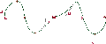
Align By Project
-
- Project the tangents of the modified surface onto the tangent plane of the other surface at the common boundary.
-
- This option is useful when aligning an isoparm to a curve on surface or trim edge. It avoids unwanted deformation of the surface, but does not guarantee tangent continuity.
Insert at Param
-
- Insert an edit point at the join point (when using the Join Parameter option) if one does not already exist. This allows you to later use the Detach tool at that point.
|
|
This option appears when
Partial Joins is on.
|
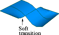
Attach Hardness
>
|
Note:
|
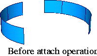
When surfaces are partially aligned and Partial Joins is on,
the Align controls are applied only to the area where the two
surfaces match up. The Attach Hardness option lets you
control the transition between the aligned part and the rest
of the surface.
|
|
|
|
Hard
-
- Only modify the area of the surface corresponding to the part of the edge that is aligned.
-
- This option creates a hard edge (multi-knot crease) between the aligned part and the rest of the surface.
|
|
|
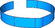
Soft
-
- Modify more of the surface than just the aligned part. This option does not create a multi-knot crease.
Control Sliders
>
|
Note:
|
Some of these sliders are incompatible with each other. For
example, if you use the Tangent Scale slider, the Join
Parameter slider will disappear.
|
|
|
To return to the initial situation where all sliders are
available, click the section's Reset button twice.
|
|
|
|
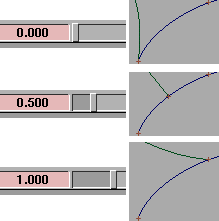
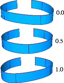
Join Parameter
-
- (This slider is not available if you use Tangent Scale or Curvature Scale.)
-
- Align the curves at a point along the interior of the other curve, rather than at the endpoint.
-
- Move the slider back and forth to move the join point along the curve interactively.
- This slider only appears for a curve that is not being modified (for example, when Position and Tangent are Modify First, the slider will appear for the second curve, and vice versa).
- The Insert at Param option (in the Toggles menu) lets you create an edit point at the join point.
|
|
This slider is not available if
you use Join Parameter.
|
Tangent Scale
-
- Change the tangent magnitude at the aligned endpoints.
-
- Move the slider back and forth to adjust the magnitude interactively.
|
|
This slider is not available if
you use Join Parameter.
|
Curvature Scale
-
- Change the amount of curvature at the aligned endpoints.
-
- Move the slider back and forth to adjust the curvature interactively.
|
|
These sliders only appear
when aligning surfaces.
|
Proportion Sliders
|
Tip:
|
The Extra CV Rows and Decay Degree sliders control how
much of the surface is affected by creating continuity at the
edges (similar to the Proportional Mod tool).
|
Extra CV Rows
-
- The number of extra rows of CVs that are modified.
-
- For example, creating curvature continuity normally modifies the third CV from the endpoint. If Extra CV Rows is set to 1, it will modify the third and fourth CVs.
Decay Degree
-
- The "speed" at which the extra modifications of Extra CV Rows fade as they travel along the curve.
-
- For example, at Decay Degree of 1, each extra CV will move half as far as the previous one. At 2, each extra CV will move one quarter as far. At 3, each extra CV will move one ninth as far.
Skew Sliders
|
|
These sliders appear when
Skews Allowed is on in the
Toggles menu.
|
Skew 1/Skew 2
-
- Amount of skew for side edges of a surface.
-
- Move the slider back and forth to adjust the magnitude interactively.
Control Options
Create History
-
- Save the Align history of these two objects for later editing, and maintains the alignment if the objects are modified by other tools.
|
|
You can also use the Query
edit tool (see page 50) to
bring back the Align Control
window.
|
-
- If Create History is on, you can later re-select the two objects followed by the Align tool (or vice-versa). This will bring up the Align Control window where you can change the alignment options, and the objects will update.
Continuity Check
-
- Turn on the surface continuity checker for the edges being aligned. This persistent locator measures and displays any discontinuities (positional, tangent or curvature) between the two surfaces.
See Also
|
Object Edit >
Attach >
Attach

|
Attaching Objects
|
|
|
|
|
Purpose
- Join curves by connecting their endpoints
- Join surfaces by connecting the edges
- Close a surface by connecting opposite edges
How To
|
|
|
To attach two curves or surfaces:
-
1
-
Click the Attach icon, or choose Attach > Attach from the Object Edit palette menu.
-
2
-
Pick the first curve, or an edge of the first surface.
-
Click as close as possible to the end of the curve or surface
where the two objects will attach.
-
3
-
Pick the second curve, or an edge of the second surface.
-
Click as close as possible to the end of the curve or surface
where the two objects will attach.
To close a curve or surface by attaching two edges:
-
1
-
Click the Attach icon, or choose Attach from the Object Edit palette menu.
-
2
-
Pick an edge of the surface or the end of a curve.
-
3
-
Click the edge opposite the one you clicked in step 2.
>
|
Note:
|
You must have at least four spans (not counting multi-knots)
between the opposite edges of the surface to attach them.
|
Tips and Notes
- When you choose surface edges to attach, try to click near the same end of each edge. If you click at opposite ends, the Attach tool will twist the surface to attach the ends you clicked.
- If you can't click the exact edge of a surface, click the closest isoparm.
|
|
Multi-knots are multiple edit
points at the exact same
location
|
- If you attach curves with different degrees, the resulting curve will have the higher degree and contain multi-knots.
- Use the Knot Insertion option to reduce some of the problems associated with attaching objects with different endpoint tangent magnitudes or degrees.
Options
|
|
|
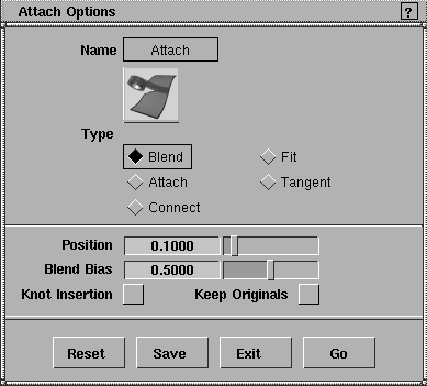
|
|
|
Type
|
|
|
Blend
-
- Modify both objects by blending their endpoints/edges to attach them. You can control the weighting of how much each object will be modified with the Blend Bias option (see below).
|
|
|
Fit
-
- Modify only the second object you picked to attach its endpoints/edges to the first object.
-
- The higher the degree of the geometry, the more the object will be modified. This option is not recommended for degree 7 geometry.
|
|
|
Attach
-
- Create additional spans between the two objects (with the number of spans equal to the degree of the resulting object) to attach them. This option does not change the shapes of the original objects.
|
|
|
Tangent
-
- Create one additional span between the two objects to attach them. (Degree 1 and 2 geometry is an exception and requires three and two extra spans respectively.) This option maintains the shape and end tangent direction of the original objects.
-
- The new span is connected to the original objects with multi-knots. Attempts to edit the resulting object at the attachment points may result in cusps.
|
|
|
Connect
-
- Create a single, straight span between the objects to attach them. If the endpoints of both objects already coincide, they are simply joined together with a multi-knot.This option does not modify the shapes of the original objects.
-
- The new span is connected to the original objects with multi-knots. Attempts to edit the resulting object at the attachment point(s) may result in cusps. The Knot Insertion option has no effect with the Connect type.
Other Controls
Position
-
- Percentage distance (0 to 1), along the last span of the objects being attached, where new edit points are inserted when Knot Insertion is on. The default is 0.1000.
|
|
|
Blend Bias
-
- (This option is only used by the Blend type).
-
- The percentage preference (weighting), from 0 (first object only) to 1 (second object only), between the two original objects when blending.
- A value of 0 moves the end of the first object to the end of the second object.
- A value of 0.5 modifies both objects equally so their ends meet halfway.
- A value of 1 moves the end of the second object to the end of the first object.
Knot Insertion
-
- Insert additional edit points near the ends of the curves to create smoother attachments (decrease the probability of Attach having to modify the shape of the original objects).
Keep Originals
-
- On-keep the original objects in addition to the new, combined object.
-
- Off-delete the original objects after the Attach operation is complete.
See Also
|
Object Edit >
Attach >
Detach

|
Detaching Objects
|
|
|
|
|
Purpose
Separate a curve or surface into two objects at an edit point or isoparm.
How To
To separate an object at an isoparm or edit point:
-
1
-
Click the Detach icon, or choose Attach > Detach from the Object Edit palette menu.
-
2
-
Click the object at the point you want to detach:
- For curves, click an edit point.
- For surfaces, click an isoparm.
Options
Keep Originals
-
- On-keep the original object in addition to the new, detached objects.
-
- Off-delete the original object after the Detach operation is complete.
See Also
|
Object Edit >
Close

|
Making Objects Open or Closed
|
|
|
|
|
Purpose
Convert an open curve or surface to closed, or a closed curve or surface to open.
How To
|
|
|
To open or close a curve:
-
1
-
Click the Close icon, or choose Close from the Object Edit palette menu.
-
2
-
Click an open curve to close it. Click a closed curve to open it.
|
|
|
To open or close a surface:
-
1
-
Click the Close icon, or choose Close from the Object Edit palette menu.
-
2
-
Click an open surface to close it. Click a closed surface to open it.
- Click a U isoparm to open/close the surface in the U direction.
- Click a V isoparm to open/close the surface in the V direction.
- Click both types of isoparm to open/close the surface in both directions.
Tips and Notes
- To find out if a curve or surface is closed, look under Geometry info in the Information Window or use the Query edit tool.
- Alias distinguishes between objects that merely look closed (their start and end points occupy the same space) and objects that have a periodic topology (the control hull coils over itself with several end CVs overlapping) which cannot be opened by simply moving CVs. The Close tool produces the latter. This distinction can become very important when applying shaders.
Options
Preserve Shape
-
- On-add or delete edit points to preserve the object's shape.
-
- Off-close without adding edit points.
See Also
|
Object Edit >
Insert

|
Inserting New Points or Isoparms
|
|
|
|
|
Purpose
Insert additional edit points on a curve, or additional isoparms on a surface.
How To
To add edit points to a curve:
-
1
-
Click the Insert icon, or choose Insert from the Object Edit palette menu.
-
2
-
Click the curve where you want to add the new edit point.
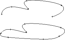
- Hold the Alt key and click to place the edit point at the midpoint of a span (halfway, in parametric distance, between the surrounding edit points).
|
|
|
-
3
-
A locator appears on the curve.
- Drag the mouse to move the locator. The prompt line shows you the exact curve parameter of the locator. (See Parameterization on page 10).
- Type a value to move the locator to that exact parameter on the curve.
-
4
-
Click the Go button in the lower right corner of the view window to add the new edit point.
-
5
-
Insert adds the edit point and the locator remains active. You can repeat step 3 to add more edit points, or choose a new tool.
To add isoparms to a surface:
-
1
-
Click the Insert icon, or choose Insert from the Object Edit palette menu.
-
2
-
Click the surface where you want to add the new isoparm.
- Click a U isoparm to add a new U isoparm.
- Click a V isoparm to add a new V isoparm.
- Hold the Alt key and click to place the isoparm at the midpoint of a span (halfway, in parametric distance, between the surrounding isoparms).
|
|
|
-
3
-
A locator appears on the surface.
- Drag the mouse to move the locator. The prompt line shows you the exact U or V parameter of the isoparm.
- Type a value to move the locator to that exact U or V parameter on the surface.
-
4
-
Click the Go button in the lower right corner of the view window to add the new isoparm.
-
Insert adds the isoparm and the locator remains active. You
can repeat step 3 to add more isoparms, or choose a new
tool.
-
|
|
Warning: multi-knots often
have undesirable effects. See
Multi-knots and CV
Multiplicity on page 9 for
details.
|
|
Tip:
|
To create a multi-knot on a curve or surface, simply insert an
edit point or isoparm twice at the exact same parameter
value.
|
|


