Introduction |
|
||
1 |
Background Information |
In This Section:
Special thanks to Martin Watt and the authors of the Learning Alias book for the material upon which this chapter is based. Introduction to Curve Geometry |
|
|
| |||
>
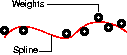
History of SplinesSplines are types of curves, originally developed for ship-building in the days before computer modeling. Naval architects needed a way to draw a smooth curve through a set of points. | |||
|
|
The solution was to place metal weights (called knots) at the control points, and bend a thin metal or wooden beam (called a spline) through the weights. The physics of the bending spline meant that the influence of each weight was greatest at the point of contact, and decreased smoothly further along the spline. To get more control over a certain region of the spline, the draftsman simply added more weights. This scheme had obvious problems with data exchange! People needed a mathematical way to describe the shape of the curve. Cubic Polynomials Splines are the mathematical equivalent of the draftsman's wooden beam. Polynomials were extended to B-splines (for Basis splines), which are sums of lower-level polynomial splines. Then B-splines were extended to NURBS. Mathematical Representations of CurvesPolynomial EquationsStarting with the simplest mathematical representation, we all remember from geometry class that we can represent a (two dimensional) line with an equation like y = 2x. For each value of x, we multiply it by 2 to get the value of y, and plot the two values on a graph. The generalized form of this type of equation is ax + by = c. The expression to the left of the equals sign is called a polynomial ("poly" means many. It refers to the fact that the expression has more than one term). We can make more complicated expressions where x is multipied by itself, like y = x*x*x. Instead of writing out all the x's in a term, we usually just count them and write the count as a superscript. The superscript is called "the exponent". The expression above would then be written as y=x3
We can write polynomials with exponents, such as: DegreeThe degree of a polynomial equation is the largest exponent in the equation. Recall that the largest exponent on the equation for a line was 1 (when a term has no exponent, it is the same as an exponent of 1). So the degree of a linear equation is 1. A quadratic equation, which has a term x2, is degree 2. A cubic equation, which has a term x3, is degree 3, and so on. Parametric Representations
There are two general ways to write an equation for a curve. The implicit representation combines every variable in one long, non-linear equation, such as: In this representation, to calculate the x and y values to plot them on a graph, we must solve the entire non-linear equation.
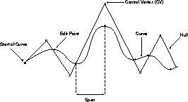
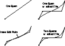
The parametric representation rewrites the equation into shorter, easily solved equations that translate one variable into values for the others: Using this representation, the equations for x and y are simple. We just need a value for t, the point along the curve for which we want to calculate x and y. You can visualize parametric curves as being drawn by a point moving through space. At any time t, we can calculate the x and y values of the moving point. This is a very important point, because the concept of associating a parameter number with every point on the line is used by many tools. This corresponds to the U dimension of the curve. Creating Complex CurvesThe lower the degree of a curve equation, the simpler the curve described. What if we want to represent complex curves? The simple answer might be to increase the degree of the curve, but this is not very efficient. The higher the degree of the curve, the more computations are required. Also, curves with degree higher than 7 are subject to wide oscillations in their shape, which makes them impractical for interactive modeling. The answer is to join relatively low-degree (1 to 7) curve equations together as segments of a larger, more complex composite curve. The points at which the curve segments, or spans, join together is called an edit point. | ||
|
Degree 5 and degree 7 curves are only available in some products or as purchasable options. |
Higher degree curves should not be completely discounted, however. Degree 5 and 7 curves have certain advantages such as smoother curvature and more "tension". They are often used in automotive design. Smooth JoinsA type of curve developed in the auto industry and familiar to anyone who works with common illustration programs is the Bezier curve. Bezier curves combine cubic curve segments, each with four control points (the start and end points, and two "handles"). The problem with Bezier curves is that the joins between segments are not necessarily smooth. The solution to this problem, used by NURBS, is to use the last control points of the previous span as the first control points of the current span. This ensures smooth joins between curve segments. (Bezier curves can still be simulated perfectly using NURBS curves with multi-knots). The degree of the curve determines the smoothness of the joins between spans. Degree 1 (linear) curves give positional continuity at the join. Degree 2 (quadratic) curves give tangent continuity. Degree 3 (cubic) curves give curvature continuity. NURBSNURBS stands for Non-Uniform Rational B-Splines. Non-Uniform refers to the parameterization of the curve. Non-Uniform curves allow, among other things, the presence of multi-knots, which are needed to represent Bezier curves. Rational refers to the underlying mathematical representation. This property allows NURBS to represent exact conics (such as parabolic curves, circles, and ellipses) in addition to free form curves. Finally, B-splines, as mentioned above, are piecewise (made of multiple pieces) polynomial curves that have a parametric representation. The next few sections explain all of these concepts. Understanding Curves | ||
|
| |||
To understand and fully use the modeling tools, you should understand the following properties of curves.
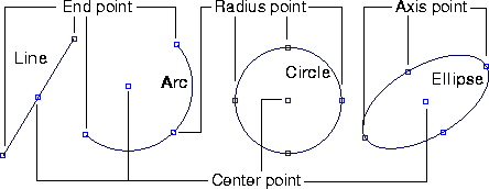
Control PointsEdit PointsInternally, Alias creates curves by joining together polynomial curve segments. The points at the joins between segments are called edit points (sometimes also called knots, although formally, a knot is the parameter value at the edit point). Edit points lie directly on the curve. The curve segments between edit points are called spans. Adding edit points does not change the shape of the curve, but adds more control points (CVs), so more edit points means finer control of the curve. Conversely, removing edit points represents a loss of information, and may change the shape of the curve. CVsCVs (control vertices) control how the curve is "pulled" from a straight line between edit points. They are the most basic and important means for controlling the shape of a curve. Lines between consecutive CVs form the control hull. You cannot add CVs to the interior of a curve: there is always a set number of CVs for each span. The number of CVs is equal to the degree of the curve plus one. So, for example, a degree 3 curve has four CVs per span. You can change the weight of CVs using the Adjust weight tool. This affects the degree to which the CV "pulls" the curve. When you model with Non-rational geometry, the system may use differently weighted CVs to achieve greater precision. In practice, weighting CVs causes several problems. See Rational vs. Non-rational Geometry on page 13. Moving Edit Points vs. Moving CVsIn theory, moving edit points would be an excellent way to edit a curve, since they lie on the curve itself. Unfortunately, it doesn't work out that way. This is because the shape of the curve determines the positions of edit points, not the other way around. Alias does allow you to move edit points by "reverse engineering" the curve from the edit point. When you move an edit point, the Move tool tries to find a curve which passes through the new edit point location. Because this process is time-consuming and has an infinite number of solutions, the tool must place constraints on how moving the edit point affects the curve. Because of these constraints, you usually cannot make major changes well by moving edit points. Moving edit points is best for small scale reshaping. Even though it is slightly less intuitive, the only way to reshape the curve with complete power is by moving CVs. Multi-knots and CV MultiplicityA multi-knot consists of multiple edit points at the same location in space. CV multiplicity refers to the number of CVs at the same location in space. Multi-knots are usually the result of curve or surface editing operations that require a sharp turn in a curve. CV multiplicity is controlled by the Multiplicity tool. Multi-knots and CVs with multiplicity are generally undesirable. Some tools (such as Birail) cannot work with them, and many CAD packages will not accept models with multi-knots. Multi-knots and CV Multiplicity achieve similar effects, even though they are different mathematically. Multi-knots and Continuity | |||
|
See Continuity on page 23 for more information on continuity. |
Multi-knots destroy one level of continuity for each extra edit point. For example, a degree 3 curve normally has curvature continuity (G2) at edit points. | ||
|
Alias only creates full multiplicity knots, i.e. knots which have a multiplicity equal to the degree of the curve. |
ParameterizationIdeally, you would not have to worry about the underlying geometric representation of curves. Unfortunately, in return for the power of NURBS, you must sometimes deal with exactly how a curve or surface is being represented mathematically. Every point on a curve has a number, called its parameter. This is the point's location in the U dimension of the curve (see the earlier discussion on Polynomials). The parameters let you specify an exact point on the curve. The higher the number, the further is the point along the curve. Alias uses two methods for deciding the parameterization (sometimes called knot spacing) of the curve. That is, how to equate parameter numbers with points along the curve. The methods are called Uniform and Chord-length parameterization. Curves with different parameterizations can look identical, but have different underlying structure, as illustrated below. | ||
|
|
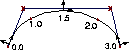
UniformUniform parameterization assigns integral parameter values to the edit points, and evenly distributes parameters along the spans between edit points. So, the first edit point is always parameter 0.0, the second edit point is always 1.0, the third is always 2.0, and so on (hence, the parameter value of the last edit point always indicates the total number of spans in the curve). | ||
|
|
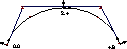
Chord-lengthChord-length parameterization assigns parameter 0.0 to the start of the curve, then increases the parameter value proportionally to the chord length between successive edit points. (The chord is the straight line between two successive edit points.) The edit points therefore have irregular parameters.
Comparison
| DegreeHigher degree curves have more control points and keep better continuity between the segments of the curve. Lower degree curves are faster to compute.
The default and most commonly used curve is degree 3. Use degree 1 for objects with flat facets. Use degree 2 if you don't require curvature continuity. Degree 5 and degree 7 curves are generally used in automotive design. They are slower, but give you smoother curves, better internal continuity, and more control. Curvature | |
|
|
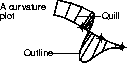
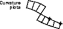
Curvature is measured by fitting a circle into the curve, then taking the reciprocal of the circle's radius. In the illustration at left, at point x, the curve is best described by a circle with radius r. At this point, the curvature is 1/r. (We use the reciprocal, 1/r, instead of just r because a flat line has an infinite radius. Taking the reciprocal gives us 0 instead of infinity.) | ||
|
|
Several tools in Alias, most notably the Curve curvature tool, allow you to display a comb plot of a curve's curvature. At regular points along the curve, the tool samples the curvature, and draws a line (sometimes called a "quill" because it looks like a spine on the back of a porcupine). The length of the line represents the curvature value at that point. Rational vs. Non-rational Geometry | ||
|
| |||
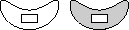
Non-rational geometry is a sum of polynomials. Rational geometry is a ratio of sums of polynomials. Rational geometry is considerably more complex mathematically. Therefore:
The following tables lists the differences between the two types of geometry.
| |||
|
|
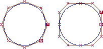
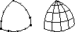
The illustration at left shows two circles drawn with the two types of geometry.
You can see the difference in two ways:
| ||
|
|
Tips for Constructing Quality Curves | ||
|
| |||
To create quality surfaces you need quality curves. These guidelines will help you create good curves: Simple CurvesUse the simplest curves that can describe the shape you want. Simpler curves mean simple, faster rendering surfaces. One effective method for achieving simple curves is: | |||
|
|
This iterative process ensures your curve only has as many spans as are absolutely necessary. You can also use the Rebuild curve tool to simplify existing curves. The tool can simplify a curve while maintaining its shape within a tolerance you set. ParameterizationIt is often best to build curves with uniform parameterization, because it makes inserting edit points and detaching curves at exact locations easier.
IntersectionsSome surfacing tools require curves to intersect:
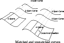
Planning for SurfacesPlan ahead to the surfaces you want when creating curves. Try to have the same number of spans in all the construction curves you use to build a surface. A simple way to achieve this is to start with one curve, then duplicate it to create more construction curves. When you create a surface from curves with different numbers of spans, the new surface will have an extra isoparm corresponding to every extra edit point. This is known as cross knot insertion. It makes the new surface more difficult to edit and more complex.
Keypoint Curves | ||
|
| |||
Overview | |||
|
|
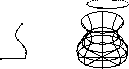
Anatomy of a Keypoint Curve
Understanding Surfaces | ||
|
| |||
Curves are the basis of 3D modeling, but curves do not render. To actually create a visible scene, you must create surfaces. Description | |||
|
|
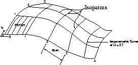
Seen one way, surfaces are curves with an extra dimension. A curve has one dimension: length (called the U dimension). A surface has two dimensions: length and width (called U and V). A NURBS surface is displayed as a mesh of curves, called isoparms, running in the U and V directions. The isoparms define four-sided regions called patches, which are the equivalent of spans on curves. Surfaces are created from curves in different ways by different tools. There are five basic types of surface creation tools. Each uses a different method for turning curves into surfaces. | ||
|
|
| ||
|
|
| ||
|
|
| ||
|
|
| ||
|
|
Surface Properties
IsoparmsIsoparm is short for isoparametric curve. Unfortunately, the term "isoparm" is used to describe two related but subtly different features of a surface:
You can display a surface with a large number of isoparms of the first type visible, but only some of those are of the second type. PatchesThe regions between the second type of isoparms are called patches. You rarely need to think about patches, since the focus is on the isoparms. One tool that works with patches is the Patch precision tool, which sets how many U and V isoparms are drawn for each patch. UV and NormalsJust as every point along the length of a curve has a U parameter, every point across a surface has a pair of (U,V) parameters. The parameterization of the surface depends on the parameterization of the curves from which it was constructed, and how it was constructed. Normals are imaginary lines perpendicular to each point on the surface. The direction of U and V isoparms on the surface determines the direction of the surface normals. | ||
|
|
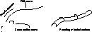
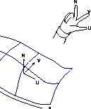
You can visualize the direction of the normal using the "right-hand rule." Point your right thumb in the increasing U direction and your right forefinger in the increasing V direction. Point your middle finger perpendicular to your thumb and forefinger, and you have the surface normal direction.
Some situations require U and V to run in specific directions.(For example, when you apply a parametric texture map to a surface, the mapping of the image to the surface depends on the orientation of U and V.) The normal is often used as a way of specifying which side of a surface points "inside" or "outside" (for example, when creating shells.) If a texture map appears inverted on a surface, reversing the UV direction of the surface is one way to correct the problem. Parameterization and DegreeThe U isoparms and V isoparms can have different parameterization and/or degree. For example, the U isoparms of a surface can be degree 3 with uniform parameterization, while the V isoparms are degree 1 with chord-length parameterization. SidednessTechnically, and counter-intuitively, NURBS surfaces have only one side (the side that faces the direction of the normal). When viewed from the other side, the surfaces are invisible. To save you from having to worry about which direction your surfaces are facing, Alias renders "double-sided" surfaces. When rendering, Alias creates an opposite-facing double of every surface in the scene. You can turn this feature off for individual surfaces (in the Render Stats window), to save rendering time. What NURBS Surfaces Can't DoBecause of the underlying representation of NURBS surfaces, there are some things they cannot model:
Curves-on-SurfaceCurves-on-surface are special curves that are drawn in the UV space of a surface, rather than in the XYZ space of the scene. Curves-on-surface do not have CVs. They are controlled by moving on curve edit points. You can create curves-on-surface by drawing directly on the surface, by projecting existing curves onto a surface, and by intersecting existing geometry with a surface. Curves-on-surface are usually used to trim surfaces, or to form the edge of new surfaces. Continuity | ||
|
| |||
Continuity is a measure of how well two curves or surfaces "flow" into each other. How To Use Continuity and Curve Degree
Types of ContinuityContinuity is a mathematical indication of the smoothness of the flow between two curves or surfaces. The following lists the five types of continuity possible with Alias tools, G0 to G4. Note that G3 and G4 continuity are only available with blend curves. See Introduction to Blend Curves on page 408. | |||
|
|
| ||
|
|
| ||
|
|
| ||
|
|
| ||
|
|
| ||
|
|
Shells and Faces | ||
|
| |||
Alias has two special types of surfaces in addition to regular NURBS surfaces: shells and faces. FacesFaces are very lightweight objects. They are always planar and render very quickly. Faces are represented in the edit windows by a thick border curve. Faces are specialized objects and are not supported by most tools that work on surfaces. Faces have no V parameters or isoparms. In many cases, unless you are trying to reduce file size and rendering time, you will want to use planar trimmed surfaces instead. You can create faces using the Set planar tool (see Making a Planar Face from Bounding Curves on page 224). Faces are also sometimes created by other tools such as Extrude to add planar "caps" to other surfaces. ShellsShells are collections of adjacent NURBS surfaces. Every surface stitched into a shell must meet the edge of another surface in the shell at some point. Shells are stored as a single node in the DAG. Shells can be open or closed. For closed shells, the normals should always point outward. This is necessary for the Boolean operations. The main uses of shells are:
Shells have the following limitations:
| |||
| Copyright © 1998, Alias|Wavefront, a division of Silicon Graphics Limited. All rights reserved. | Please send questions or comments regarding the documentation to: [email protected] |