![]()
![]()
![]()
![]()
![]()
![]()
![]()
![]()
![]()
![]()
|
|
|
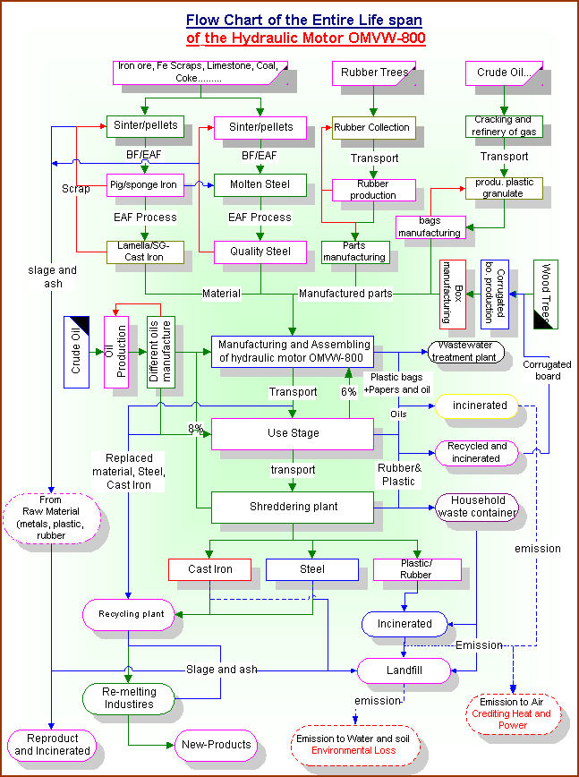
| Scope definition of the product system The
purpose of this section is to describe the processes in the life cycle of the
hydraulic motor OMV/W-800. These processes are illustrated in figure (3.5).
In figure (3.5), one can see the processes that are involved in
the different stages i.e. raw materials, manufacturing, use and disposal stages
of the hydraulic product. The
detailed study on these processes in the different stages is reported in
appendixes and important brief explanations on each stage processes are reported
and their importance is briefly discussed below:
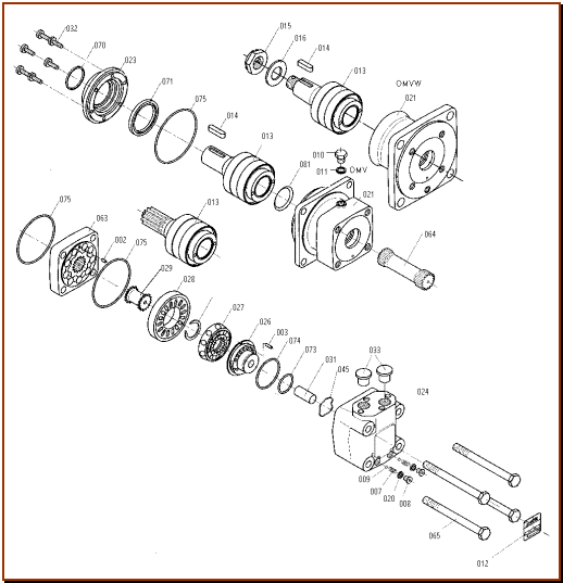
A hydraulic motor OMV/W-800 consists principally of eight main parts e.g. gear set, motor house, output shaft, distributor valve, channel plate, balance plate, valve house and cardan shaft. Some of the parts further consist of numerous components, for example: the gear set contains gear wheel, gear rim and 9 rollers. The exploded view of the hydraulic motor illustrates installed components in the hydraulic motor figure (3.6). All components are specified with item numbers and described in table (3.2) in the product’s parts list on the following pages.
Figure (3.6):
Exploded view of the hydraulic
motor OMV/W-800. A hydraulic motor
OMV/W-800 converts hydraulic energy into mechanical energy by functioning the
different parts as shown in exploded view. Main functions of the parts: The
distributor valve (027) has been separated from the output shaft (013), which is
driven by a short valve drive (029). A balance plate (026) counterbalances the
hydraulic forces around the distributor valve.
The internal gear
(063) through a cardan shaft (064) ensures that the individual chambers of the
motor are filled and emptied precisely and drives the distributor valve (027)
synchronously (please
view the movie in CD Rom under the title “Disc_valve”).
The disc valve (027) has been integrated with the output shaft (013) through the
valve drive (029). The cardan shaft (064) must therefore rotate the disc valve
(027) as well as transfer mechanical energy from the gear wheel set (063) to the
output shaft (013). The disc valve (027) is placed between the balance plate
(026) and a channel plate (028). Hydraulic forces are equalized by the balance
plate (026). 0.1.1.1.1
Motor efficiency
As
shown in figure (3.2) above, the hydraulic pump provides hydraulic pressure and
the hydraulic oil functions through drainpipes and converts hydraulic fluid
energy into mechanical energy. The
motor runs with different efficiencies in the application (low pressure -
high efficiency, high pressure - low efficiency) as illustrated in graph figure
(3.3). The full hydraulic system containing the hydraulic pump, hydraulic valve, drain pipes loses 30% of its efficiency (Tom Tychsen, company supervisor), but the average 14% efficiency lost by the hydraulic motor (company literature) is included in the calculation, the remaining 16% efficiency is neglected (out of system boundaries). In other words, the hydraulic motor’s average efficiency (86%) is included in this study and external system efficiency in not included. The total hydraulic motor efficiency is comprised with two different losses: ¨ Mechanical losses ¨
Volumetric losses. The mechanical losses means: the pressure loss by frictions i.e. gear set, bearings and shaft seal and the pressure loss in the valve system, where the frictions include the roughness of the parts (small frictions on the parts), motor-drain flow complexity in the hydraulic product system and bad displacement timing between parts, which very often occurs between 3-6 degrees (Tom Tychsen, company supervisor). The volumetric losses means: internal leakage mainly in the gear set due to gaps between the gearwheel, gear rim and rollers and the frictions on these parts. It is also the cause of distributor valve timing: the distributor valve leaks the pressure in the gear set chamber due to the bad displacement timing. In other words, the pressure is lost due to the tightness and roughness of the parts calls volumetric efficiency. Total
efficiency of the hydraulic motor can be calculated by multiplying volumetric
efficiency and mechanical efficiency.
0.1.1.1.2
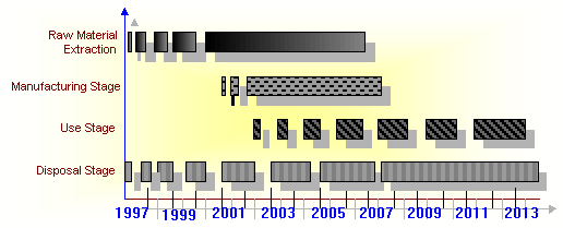
The time horizon
The
time perspective for the LCA is the sum of the different stages throughout the
life cycle. The time horizon for raw material stage from refining to production
is assumed to be 4 years. The manufacturing time is assumed to be 1 year, which
includes the storage, manufacturing and distribution and distributors storage
time. The use stage of the hydraulic product covers 8.31 years including
replacement, where the parts are replaced almost after 6 months in different
applications (see
appendix C, chapter 2, section (2.1)).
After use the hydraulic motor is disposed and steel and cast iron parts are
crushed and recycled. The rubber parts are incinerated. Figure
(3.8)
demonstrates the materials flow and disposed materials in each stage. Disposal
materials are assumed to be returned to the recycling plant after almost 1 year,
which is a little high for the manufacturing stage use, but for the full product
after use it looks reasonable in the different countries.
Figure
(3.7): Disposal planning of the hydraulic motor. As
shown in figure
(3.7),
the time horizon for the hydraulic product system is estimated to be almost 11.5
years from raw material refining to metals recovery for the different stages,
which will be shorter than the time horizon affects caused by the potentials
impacts on the environment. For example, the effect from the global warming will
be hundreds of years. The time horizon of the validity of the LCA also depends on application. If the application lifetime is shorter, then the time horizon of the hydraulic product will also change. Finally the hydraulic motor’s time horizon very much depends on the application, in which it is installed.
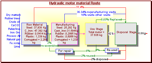
Figure (3.8): Material Route
from cradle-to-grave of the hydraulic product system. |
Send mail to [email protected] with
questions or comments about this web site.
|