|
|
Shading Surfaces
|
|
|
6
|
Shaders
|
|
Shaders determine what surfaces look like (for example, color, reflectivity, roughness). Once you create a shader, you can assign it to one or more surfaces. You can also layer more than one shader onto a single surface.
In This Section:
Assigning or Layering a Shader
|
|
|
|
|
In order for a surface to have the properties of a shader, you must assign the shader to the surface. You can assign a single shader to several different surfaces. You can also layer several shaders onto a single surface. By default, all surfaces have the DefaultShader assigned to them.
To assign a shader to a surface:
-
1
-
Pick the surface(s) in a modeling window.
-
2
-
Pick the shader in the Multi-lister.
|
|
See Assign Shader on page 30.
|
-
3
-
Select Shading > Assign Shader in the Multi-lister.
To layer shaders onto a surface:
-
1
-
Pick the surface(s) in the modeling window.
-
2
-
Pick the shader in the Multi-lister that you want to layer another shader on top of.
|
|
See Assign Shader on page 30.
|
-
3
-
Select Shading > Assign Shader in the Multi-lister.
-
4
-
Pick the shader in the Multi-lister that you want to be layered on top of the first shader.
|
|
See Layer Shaders on page 31.
|
-
5
-
Select Shading > Layer Shaders in the Multi-lister.
Reflection Mapping a Shader
|
|
|
|
| |
|
See Reflection on page 76.
|
Normally the renderer only calculates reflections during raytracing. However, you can map an image file or texture directly to a BLINN or PHONG shader's Reflection parameter to simulate reflections during raycasting or raytracing. For example, you can use an environment texture as a reflection map to simulate environmental reflections. Another use of reflection maps is to produce identical reflections on several surfaces.
|
|
See Render Overview on
page 428.
|
By default, reflection mapping only works during raycasting. To use reflection maps during raytracing, you must set the shader's Use Refl. Map parameter ON.
You can also simulate reflections on a LAMBERT shader by mapping an image file or texture to the shader's Color or Incandescence parameter.
To reflection map a shader:
-
1
-
Double-click the shader swatch in the Multi-lister to open the Control Window.
-
2
-
Click the Map button (to the right of the Reflection parameter) to open the Texture Procedures window.
-
3
-
In the Texture Procedures window, click the button of the texture you want to use.
-
The texture swatch appears in the Multi-lister, and the
texture appears on the shader swatch.
-
4
-
If you want to use the reflection map during raytracing, set the shader's Use Refl. Map parameter ON.
Shader Parameters
|
|
|
|
|
Shader Name
The name of the shader. Shader swatches in the Multi-lister are listed alphabetically (except for the DefaultShader). If you change a shader's name, the swatch display in the Multi-lister may also change.
|
|
|
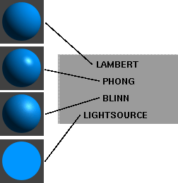
Shading Model
Defines the basic surface type (for example, matte, reflective). The default setting is LAMBERT. Each Shading Model has its own set of Shading Parameters.
| LAMBERT
| A matte surface (chalk, matte paint, or unpolished surface)
|
| PHONG
| A glassy or glossy surface (ABS or SAN copolymer which is often used for car mouldings, telephones, and bathroom fittings)
|
| BLINN
| A metallic surface (brass, aluminum)
|
| LIGHTSOURCE
| A special effect. Light falling on the surface is summed and averaged, and no complex shading is performed. The surface does not act as a light.
|
Shading Parameters
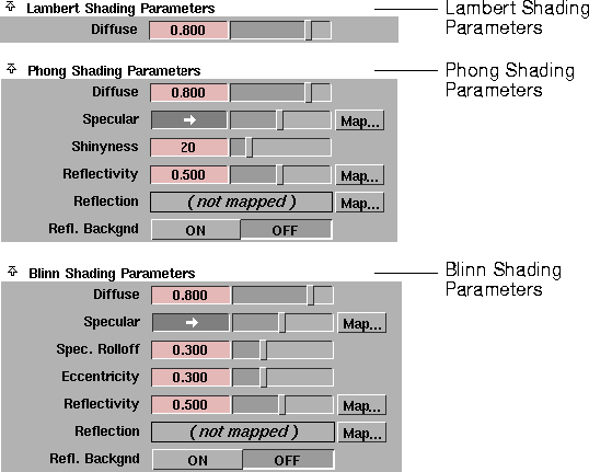
The Shading Parameters are different when Shading Model is LAMBERT, BLINN, and PHONG. There are no Shading Parameters when Shading Model is LIGHTSOURCE.
|
|
|
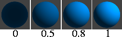
Diffuse
-
- The ability of the surface to reflect light in all directions. The Diffuse value acts like a scaling factor applied to the Color setting: the higher the Diffuse value, the closer the actual surface color will be to the Color setting. The valid range is 0 to ·. The slider range is 0 (no light is reflected in all directions) to 1. The default color Value is 0.8.
|
|
|
Specular
-
- The color of shiny highlights on the surface. A black Specular produces no surface highlights. The default color Value is 0.5.
|
Tip:
|
For glossy plastic surfaces, use a whitish Specular color. For
metallic surfaces, use a Specular color similar to the surface
color.
|
|
|
|
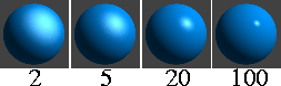
Shinyness
-
- Controls the size of shiny highlights on the surface. This parameter is only available when Shading Model is PHONG. The valid range is 2 to ·. The slider range is 2 (broad highlight, not very shiny surface) to 100 (small highlight, very shiny surface). The default value is 20.
|
|
|
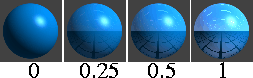
Reflectivity
-
- The ability of the surface to reflect its surroundings (the environment, other surfaces), or the Reflection map, if any. Reflectivity values for common surface materials are: car paint (0.4), glass (0.7), mirror (1), chrome (1). To help visualize the effect of Reflectivity in the shader swatch, temporarily assign a Reflection map to the shader.
-
- The valid range is 0 to ·. The slider range is 0 (no reflections) to 1 (clear reflections). The default value is 0.5.
|
Note:
|
Reflections are only calculated during raytracing.
|
|
|

|
Reflection
-
- Maps an image file or texture onto the surface to simulate reflections. By default, reflection mapping only works during raycasting. To use reflection maps during raytracing, set the shader's Use Refl. Map parameter ON.
|
|
|
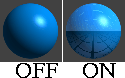
Refl. Backgnd (Reflect Background)
-
- Causes the surface to reflect the environment texture assigned to the environment. The default setting is OFF.
-
- Refl. Backgnd has no effect if an environment texture is not assigned to the environment. If Refl. Backgnd is ON, any Reflection map assigned to the surface will be ignored.
|
|
See Render Overview on
page 428.
|
-
- Refl. Backgnd has a different effect during raycasting and raytracing. During raycasting, the surface reflects the environment texture assigned to the environment. During raytracing, the surface reflects only the environment texture assigned to the environment. Any surrounding objects that would normally be reflected by the surface during raytracing will not be reflected when Refl. Backgnd is ON. If Refl. Backgnd is OFF during raytracing, the surface will reflect the environment and surrounding objects.
|
|
|
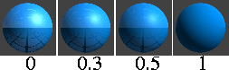
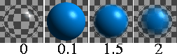
Spec. Rolloff (Specular Rolloff)
-
- The ability of the surface to reflect its surroundings (the environment, other surfaces), or the Reflection map, if any, when viewed at oblique angles. This parameter is only available when Shading Model is BLINN. To help visualize the effect of Spec. Rolloff in the shader swatch, temporarily assign a Reflection map to the shader.
-
- The slider range is 0 to 1. The default value is 0.3.
|
Tip:
|
Use a Spec. Rolloff value of 0.7 to simulate a wet surface (for
example, wet paint).
|
|
|
|
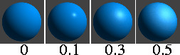
Eccentricity
-
- Controls the size of shiny highlights on the surface. This parameter is only available when Shading Model is BLINN. The valid range is 0 (no highlight) to 0.999 (broad highlight, not very shiny surface). A value of 0.1 produces a small highlight (very shiny surface). The default value is 0.3.
Common Shader Parameters
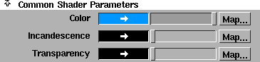
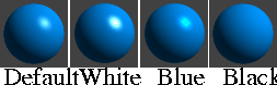
Color
-
- The color of the surface. The Color setting also defines the line color used during hidden line rendering (see Hidden Line Rendering on page 428). The default shader color is RGB (0,150,255).
|
|
|
Incandescence
-
- The color and brightness of light that a surface appears to be emitting. (Incandescent objects do not illuminate other objects.) For example, to simulate lava, use a bright red Incandescence. The default color Value is 0 (black).
|
Tip:
|
Use a little Incandescence for vegetation to make it look
alive.
|
|
|
|
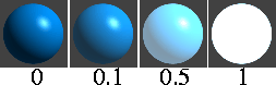
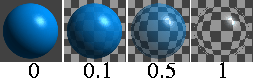
Transparency
-
- The color and level of transparency of a surface. For example, if the Transparency Value is 0 (black), the surface is totally opaque; if the Transparency value is 1 (white), the surface is totally transparent. To make an object transparent, set the Transparency color to a shade of grey or to the same color as the shader Color. The default value is 0 (black).
-
- If you change Transparency from the default black (0), the background of the shader's Multi-lister swatch will become a checkered pattern. This is a visual aid and will not be rendered in your scene.
|
Note:
|
Quick render and Toggle Shade do not display surface
transparency; transparent surfaces will appear black.
|
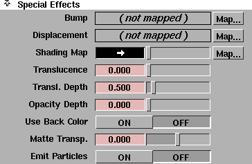
Special Effects
|
|

|
Bump
-
- Makes the surface appear rough or bumpy by altering surface normals (during rendering) according to the intensity of the pixels in the bump map texture.
-
- A bump map does not actually alter the surface. A silhouette of the surface will appear smooth.
-
- A two-dimensional bump map does not significantly increase rendering time.
|
|

|
Displacement
-
- Makes the surface rough or bumpy by altering surface normals (during rendering) according to the intensity of the pixels in the displacement map texture.
-
- Displacement mapping is similar to bump mapping, except that the surface is actually altered. (A silhouette of the surface will appear bumpy.) Displacement mapping, however, requires more rendering time than bump mapping.
-
- Be careful when positioning surfaces with displacement maps near other surfaces. Because the actual displacement takes place during rendering, parts of the surfaces may intersect.
-
- You can convert a displacement mapped surface to a polyset, and the polygons will be displaced according to the map. This is useful for positioning surfaces or camera paths before rendering. See Converting a Warped Surface into a Polygonal Surface on page 318.
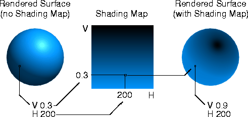
Shading Map
-
- Applies a color map to the surface after it is rendered. The U value of the Shading Map texture is mapped to the surface's hue, and the V value is mapped to the surface's intensity (the value defined by [R+G+B]/3). A shading map changes the shader's color, specular color, and eccentricity, effectively creating a new type of shading model.
-
- A Shading Map is useful for creating non-photorealistic effects (for example, cartoon shading) or for highlighting threshold values (for example, using a ramp texture).
|
|
|
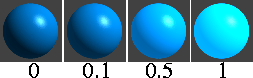
Translucence
-
- The surface's ability to transmit and diffuse light. Light falling on a translucent surface is first absorbed beneath the surface, and then diffused in all directions. The slider range is 0 to 1. The default value is 0.
-
- The Translucence value of a surface lit by a non-shadow-casting light is effectively zero or infinite (all non-zero values).
-
- If your scene combines a translucent surface with a shadow casting spotlight, faint grid-like artifacts may become visible. If this happens, increase the spotlight shadow Edge quality or lower the shadow Resolution.
-
- For high values of Translucence, lower Diffuse accordingly to avoid washout.
-
- A surface's actual translucence is based on the illumination it receives from lights, and is not related to its transparency. However, as an object becomes more transparent, its translucent (and diffuse) illumination gets dimmer.
-
- Ambient lights have no effect on translucent (or diffuse) illumination.
|
Tip:
|
Use Translucence to simulate clouds, fur, hair, marble, jade,
wax, paper, leaves, flower petals, or frosted light bulbs.
|
|
|
|
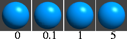
Transl. Depth (Translucence Depth)
-
- The distance light can penetrate a surface. The slider range is 0 to 5. The default value is 0.5.
-
- If the Transl. Depth value is greater than 0, light can penetrate a surface entirely and illuminate the opposite side of the surface, even though it is facing away from the light. For example, if a texture mapped spotlight shines on a plane, you will be able to see the texture on the side of the plane facing away from the light (like a rear-projection screen).
-
- The Transl. Depth value of a surface lit by a non-shadow-casting light is effectively zero or infinite (all non-zero values).
-
- If the Transl. Depth value is low (for example, 0.1) and you are raycasting with a spotlight, make sure the spotlight shadow Min Depth value is low (0.01) and the Blend Offset value is low (0.2).
|
|
|
Opacity Depth
-
- Causes the transparency of an object to diminish with its thickness. An object is opaque if its thickness is greater than its Opacity Depth value. The slider range is 0 to 5. The default value is 0.
-
- When the Opacity Depth value is 0, it has no effect (as opposed to making an object entirely opaque).
-
- The shader must have some Transparency in order to see the effect of Opacity Depth. When Opacity Depth is non-zero, then transparency will control specularity, reflectivity, and incandescence, which are normally independent of transparency. This makes it easier to create soft fuzzy objects. Also, if you want to use a transparency map to create holes in a surface that has specular highlights, set Opacity Depth to a high value, instead of creating a matching specular map.
-
- Transparent objects will cast shadows in the raycaster even if the Opacity Depth value is non-zero.
|
Tip:
|
Use Opacity Depth to simulate hair, fur, and clouds.
|
|
|
|
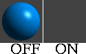
Use Back Color
-
- Assigns the color of the background that is directly behind the object to its surface. The object will then appear invisible, except for any reflections and shadows on its surface. The default setting is OFF.
-
- For example, if you are using an image file of an automotive showroom as a background, a car model will reflect this background. However, the car will not cast a shadow on the showroom floor because no actual floor exists.
-
- You can simulate a floor by placing a plane under the car model, and setting its shader's Use Back Color ON. Now the plane is invisible, except for the shadow of the car on it. If the plane's shader is reflective, the floor will also reflect the car. If you apply a transparency map to the plane that is more transparent at the edges and opaque in the center, the plane will blend nicely into the background.
Matte Transp. (Matte Transparency)
-
- A transparent multiplier applied to the surface's alpha channel in the rendered image. If the Matte Transp. value is 0, an opaque object will have an alpha value of 1 (that is, it will be entirely invisible when composited). If the Matte Transp. value is 1, an opaque object will have an alpha value of 0 (that is, it will be entirely visible when composited). For example, to make an object gradually appear during an animation (after compositing), animate the Matte Transp. value from 1 to 0.
-
- The slider range is -1 to 1. The default value is 0.
Emit Particles
-
- Causes the surface to emit particles during an animation. If Emit Particles is ON, the Particle Emission parameters become available. See Particles on page 285.
-
- If you layer two shaders that both have Emit Particles ON, particles will only be emitted from the topmost shader. To emit particles from both shaders, assign only one shader to the surface and save a particle file during the animation. Create a dummy object (for example, a point light) and assign the particle file to it. Then assign the second shader to the surface and render the animation.
Glow
The Glow parameters define the type of glow produced from light reflecting off a surface, or from surface incandescence.
|
|
|
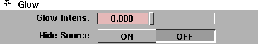
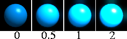
Glow Intens (Glow Intensity)
-
- The brightness of the shader glow effect. The slider range is 0 to 1. The default value is 0.
-
- Shader glow will appear different at different image resolutions. If the Environment's Glow Type and Halo Type are both off (in the ShaderGlow section of the Control Window), the Glow Intens. value has no effect (see ShaderGlow on page 58).
|
|
|
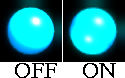
Hide Source
-
- Causes the surface to become invisible when rendered, showing only the glow effect. The default setting is OFF.
-
- If the Environment's Glow Type and Halo Type are both off (in the ShaderGlow section of the Control Window), or if the shader's Glow Intens value is zero, Hide Source has no effect (see ShaderGlow on page 58).
|
Tip:
|
Use shader glow and Hide Source to simulate gas effects
(for example, an aurora borealis).
|
Raytrace Parameters
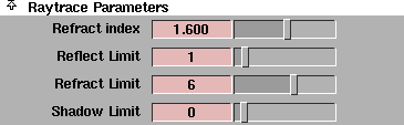
The Raytrace Parameters control the appearance of the surface during raytracing only.
|
|
|
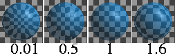
Refract Index
-
- The amount that light rays bend when passing through a transparent object. A Refract Index value of 1 does not bend light rays at all. Refract Index values for common materials are: glass (1.6), air (1), water (1.333), crystal (2), diamond (2.417). The valid range is 0.01 to ·. The slider range is 0.01 to 3. The default setting is 1.6.
-
- The shader's Multi-lister swatch only approximates the effect of the Refract Index parameter.
-
- Surfaces must have thickness in order for Refract Index to have any effect. If a surface does not have thickness (for example, a plane or face element), set the Refract Index value to 1 and use the Surface Width parameter to simulate surface thickness. See Surface Width on page 86.
-
- For best results, make sure there are suitable objects in the background to be refracted.
Reflect Limit
-
- The maximum number of times the surface will allow a light ray to be reflected. For example, if the Reflect Limit value is 4, the surface will reflect light rays that have previously been reflected (off itself or off other surfaces) 3 times or less; the surface will not reflect light rays that have previously been reflected 4 or more times. The valid range is 0 to ·. The slider range is 0 to 10. The default value is 1.
-
- Set the Reflect Limit value according to the shader's Reflectivity value. For example, if the Reflectivity value is between 0 and 0.5, set the Reflect Limit value between 1 and 2. If the Reflectivity value is between 0.5 and 1, set the Reflect Limit value between 2 and 5.
-
- High values for Reflect Limit greatly increase rendering time. Test render your scene using various settings, and use the lowest values that give you acceptable results. Even highly reflective surfaces will rarely need a Reflect Limit value as high as 10 or more.
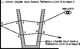
Refract Limit
-
- The maximum number of times the surface will allow a light ray to be refracted. For example, if the Refract Limit value is 10, the surface will refract light rays that have previously been refracted and/or reflected (off itself or off other surfaces) 9 times or less; the surface will not refract light rays that have previously been refracted and/or reflected 10 or more times.
-
- The valid range is 0 to ·. The slider range is 0 to 10. The default value is 6.
-
- In the following example, a glass sits in front of a mirror.
-
- The number of refractions includes both the entry and exit of a light ray from a surface having thickness.
-
- The physical property Total Internal Reflection (TIR) can make some transparent objects appear not to refract light. This is a real world property caused by light rays reflecting inside the thickness of the object. If this occurs in your model, increasing Refract Limit will have no effect, because the Reflect Limit is stopping light rays before they can exit the surface. However, because TIR is a real world property, you may want to keep this effect.
|
Tip:
|
To simulate realistic looking glass, set the Refract Limit value
to 9 or 10.
|
Shadow Limit
-
- The maximum number of times a light ray can be reflected and/or refracted for the surface to cast a shadow from that ray. For example, if the Shadow Limit value is 2, the surface will cast a shadow from light rays that have previously been reflected and/or refracted (off itself or off other surfaces) 2 times or less; the surface will not cast a shadow from light rays that have previously been reflected and/or refracted 3 or more times.
-
- The valid range is -1 to ·. The slider range is -1 to 10. The default value is 0 (the surface casts a shadow only from rays which have not been reflected and/or refracted).
|
Note:
|
High Shadow Limit values greatly increase rendering time.
|
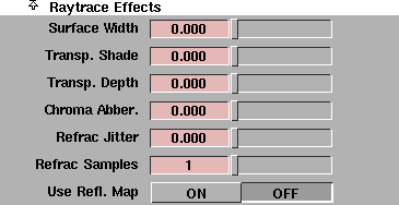
Raytrace Effects
The Raytrace Effects parameters control the appearance of the surface during raytracing only.
Surface Width
-
- The simulated thickness (in world space units) of transparent objects that are made from single surfaces (for example, a plane or face). The valid range is 0 to ·. The slider range is 0 to 1. The default value is 0.
-
- Using Surface Width does not produce the same results as building a surface with actual thickness. However, the effect works well when the edges of the surface are not visible (for example, closed surfaces, or bounded shapes like a car windshield).
Transp. Shade (Transparency Shade)
-
- Causes shadows of transparent objects to be brighter in the center, simulating the focusing of light. The valid range is 0 to ·. The slider range is 0 (constant intensity shadows) to 1 (shadows focused in the center). The default value is 0.
Transp. Depth (Transparency Depth)
-
- The distance (in world units) a light ray can travel after passing through a transparent surface. If the Transp. Depth value is 0, the light ray can travel an infinite distance. For non-zero values, after a light ray reaches the distance of the Transp. Depth value, its color becomes the background color.
-
- The valid range is 0 to ·. The slider range is 0 to 10. The default value is 0.
Chroma Abber. (Chromatic Aberration)
-
- Causes different wavelengths of light to refract different amounts when passing through a transparent surface. The valid range is 0 to ·. The slider range is 0 (no chromatic aberration) to 1. The default value is 0.
-
- Chromatic aberration only affects light rays as they pass through the second surface of a transparent object (that is, the first exit ray). For best results, make sure there are suitable objects in the background to be refracted.
|
|
|
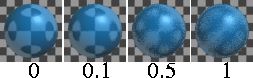
Refrac Jitter (Refraction Jitter)
-
- Randomly alters the direction of refracted light rays. The valid range is 0 to ·. The slider range is 0 (no jitter) to 1. The default value is 0.
-
- If the Refrac Jitter value is high, you may have to increase the Refrac Samples value to reduce the appearance of aliasing artifacts.
|
Tip:
|
Use Refrac Jitter to simulate frosted glass.
|
|
|
|
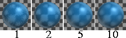
Refrac Samples (Refraction Samples)
-
- Controls the smoothness of the Refrac Jitter effect. If the Refrac Jitter value is 0, the Refrac Samples value has no effect. If the Refrac Jitter value is high, you may have to increase the Refrac Samples value to reduce the appearance of aliasing artifacts (see Aliasing on page 511).
-
- The valid range is 1 to ·. The slider range is 1 (rough) to 10 (smooth). The default value is 1.
Use Refl. Map (Use Reflection Map)
-
- Causes the surface to have reflections from the Reflection map only. If Use Refl. Map is OFF, the surface will have reflections from all of its surroundings, but not from its Reflection map. The default setting is OFF.
Hidden Line Rendering Parameters
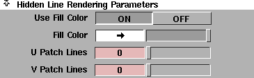
The Hidden Line Rendering Parameters control the appearance of the surface during hidden line rendering only (see Hidden Line Rendering on page 428).
|
|
|
Use Fill Color
-
- Causes surfaces to be filled with the Fill Color during hidden line rendering. If Use Fill Color is OFF, surfaces will be filled with the background color. The default setting is ON.
Fill Color
-
- The color the surface will be filled with during hidden line rendering, if Use Fill Color is ON. The default color is white.
|
|
|
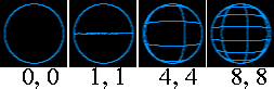
U Patch Lines, V Patch Lines
-
- The number of lines shown on the surface in its U and V directions during hidden line rendering. The valid range is 0 to ·. The slider range is 0 (no lines shown on the surface except for edge lines) to 8. The default value is 0.
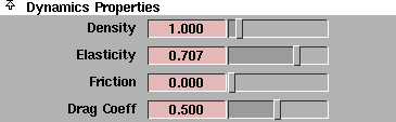
Dynamics Properties
|
|
See Dynamics on page 281.
|
The Dynamics Properties define material properties which affect how an object behaves during a dynamic simulation.
Density
-
- The density (kilograms/linear-unit3) of objects to which the shader is assigned. The Density value determines an object's mass if Use Mass/Density is set to DENSITY under Collision Types in the Run Dynamics window (see Collision Types in the Animating in Alias book), according to the formula mass = Density x bounding box volume. The slider range is 0 to 10. The default value is 1.
|
|
See Air Density on page 64.
|
-
- The Density value also determines the buoyancy of an object. An object that is less dense than the environment medium will rise.
-
- Approximate Density values (in kg/m3) for some common materials are: iron or steel (7900), aluminum (2700), glass or porcelain (2500), concrete (2400), ice (920), rubber (1000 to 1500), polyethelene (950), wood (530 to 750), water (1000), and air (1.29). Use these values as a starting point, and adjust them to refine the behaviour of objects in the dynamic simulation.
Elasticity
-
- Controls how much speed an object loses when it collides with and bounces off of another object. The slider range is 0 (all speed is lost) to 1 (no speed is lost). The default value is 0.707.
-
- Approximate Elasticity values for some common materials are: hard metals, ceramics, rubbers, or plastics (0.7 to 1), soft metals, soil, or flesh (0.2 to 0.5), any liquid (0). Use these values as a starting point, and adjust them to refine the behaviour of objects in the dynamic simulation.
Friction
-
- Controls how much speed an object loses when it rubs against another object. The Friction parameter is similar to the real-world coefficient of friction (see Wall Friction on page 65). The slider range is 0 (frictionless, no speed is lost) to 1 (all speed is lost). The default value is 0.
-
- Approximate Friction values for some common materials are: ceramic tile (0.34), aluminum (0.48), smooth cloth (0.48), paper (0.52), stainless steel (0.57), plastic (0.6 to 0.7), glass (0.61), wood (0.7 to 1), polystyrene (1). Use these values as a starting point, and adjust them to refine the behaviour of objects in the dynamic simulation.
|
|
The drag coefficient is a
measure of how much
friction an object experiences
when it travels through air
based on its shape.
|
Drag Coeff (Drag Coefficient)
-
- Controls how much speed an object loses when it travels through air. The more streamlined an object is, the lower its Drag Coeff value should be. The actual loss of speed of an object is calculated based on the Drag Coeff value, the Air Density value (see Air Density on page 64) and the cross sectional area of the object. The Drag Coeff parameter is similar to the real-world drag coefficient. The slider range is 0 (no speed is lost) to 1 (all speed is lost). The default value is 0.5.
-
- Approximate Drag Coeff values for some common shaped objects are: thin cone (0.2), sphere (0.4), cube (0.5), parachute (0.9). Use these values as a starting point, and adjust them to refine the behaviour of objects in the dynamic simulation.
|


