|
|
20
|
Rendering
|
|
In This Section:
Render Overview
|
|
|
|
|
RayCaster and RayTracer are available in Alias AutoStudio, and are purchasable PowerAnimator, Designer, and Studio options.
There are three single processor types of renderer (raycast, raytrace, and hidden line) and two multi-processor types of renderer (powercast and powertrace). You can render a scene using any of these renderers either interactively within Alias, or from a UNIX command line. You can also test render a scene at a lower resolution.
When you render a scene, the renderer first generates an SDL (Scene Description Language) file. It then uses this SDL file to create an image file. A summary of the rendering process is saved in an out file. If you are raytracing a scene, and Create Preview Image is ON (in the Render Globals window), the renderer also creates a preview image file.
Raycasting
Raycasting produces smooth shaded renderings that include shadows. Raycasting is faster than raytracing, but does not produce reflections or refraction. (You can simulate reflections using reflection maps and simulate refraction using linear transparency.) Raycasting is often required for long animations to keep the total rendering time within a reasonable limit.
Raytracing
Raytracing produces smooth shaded renderings that include reflections, refraction, and shadows.
Hidden Line Rendering
Hidden line rendering produces outline renderings of objects that are filled with flat, unshaded color. Silhouettes of surfaces include the effect of any bump or displacement maps. Hidden line rendering is useful for creating cartoon animations.
The appearance of objects that are hidden line rendered is determined by the Hidden Line Rendering Parameters in the Render Globals window and in each shader's Control Window. If Hidden Line Parms (in the Render Globals window) is PER OBJECT, then the hidden line renderer uses the Hidden Line Rendering Parameters in each object's shader (see Hidden Line Rendering Parameters on page 87). If Hidden Line Parms is GLOBAL, then the hidden line renderer uses the Hidden Line Rendering Parameters in the Render Globals window for all surfaces (see Hidden Line Rendering Parameters on page 417).
Hidden line rendering does not represent colors, textures, transparency, reflections, or shadows. The exact Anti-aliasing Levels Minimum and Maximum values (in the Render Globals window) are not relevant during hidden line rendering. Any value above 0 turns on hidden line anti-aliasing. You should set the Post Filter parameter ON (in the Blur section of the Render Globals window) when using hidden line rendering (see Post Filter on page 407).
Powercasting and Powertracing
The PowerCaster and PowerTracer are multi-processor versions of the RayCaster and RayTracer. By using the PowerCaster or PowerTracer you can render a scene using a select number of processors of a multi-processor computer. Worldspace texture mapping does not work with the PowerCaster or PowerTracer (see Worldspace on page 147).
|
Render > Render
|
Using Render
|
|
|
|
|
To render a scene using the current Rendering Options settings:
-
1
-
Select Render > Render. The File Requestor appears.
-
2
-
Type the full path and file name for the rendered image in the File Requestor, or click Show List and select the file using the File Lister. If you select a file using the File Lister, the renderer will overwrite the file with the rendered image file.
-
3
-
Click Save SDL. The renderer creates the following files:
- <pixfile> in the sdl directory (the SDL file)
- out.<pixfile> in the sdl directory (the out file)
- <pixfile> in the pix directory (the image file)
|
|
See Create Preview Image on
page 402.
|
-
The renderer may also create the file <pixfile>.test in
the pix directory (the preview image) if you are
raytracing and Create Preview Image is ON in the Render
Globals window.
-
Any errors that occur and cause the renderer to quit, are
summarized in the errlog file, which you can view by
selecting File > Show > Errlog.
|
|
You can render more than
one file at a time from a
UNIX command line.
See Command Line Rendering
on page 440.
|
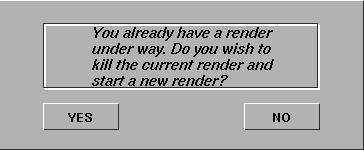
-
You can only render one file interactively within Alias. If
you start a second render before the first render is
completed, the following message appears.
To open the Rendering Options window:
- Select Render > Render
 . .
To view a rendered image at actual size (either during rendering or after rendering is complete):
- Select Render > Show render. A window appears with the partially or fully rendered image in it. If the render is not yet complete, the image continuously updates as the render progresses.
-
If the Image File Output Format is TIFF or TIFF16, Show render
cannot display the rendered image until the render is
complete (see Format on page 411).
To view a rendered image at reduced or enlarged size (either during rendering or after rendering is complete):
-
1
-
Select Render > Show render to open the Show Render Options window.
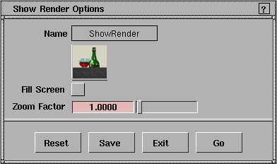
-
2
-
To view the rendered image so that it fills the screen, select Fill Screen.
-
To view the rendered image at a size smaller than actual
size, set the Zoom Factor value between 0 and 1.
-
To view the rendered image at a size larger than actual
size, set the Zoom Factor value between 1 and 20.
-
3
-
Click Go. A window appears with the partially or fully rendered image in it. If the render is not yet complete, the image continuously updates as the render progresses.
To view a rendered animation (either during rendering or after rendering is complete):
|
|
See Previewing Rendered
Animation in the Animating
in Alias book.
|
-
1
-
Select Animation > Flipbook. The File Requestor appears.
-
2
-
Use the File Requestor to select the first pix file of the animation you want to view, and click Show.
-
The Flipbook window appears and automatically displays
the rendered animation.
To abort a render in progress:
-
1
-
Select Render > Abort render. The following confirm box appears.
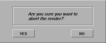
-
2
-
Click YES to abort the render, or NO to continue rendering.
Rendering Options
|
|
|
|
|
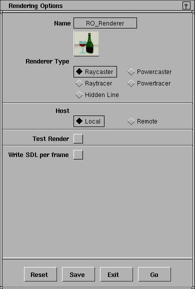
Renderer Type
-
- The type of renderer used: Raycaster, Raytracer, Hidden Line, Powercaster, or Powertracer. The icon in the Rendering Options window changes if you change Renderer Type. If Renderer Type is Powercaster or Powertracer, the Processors parameter becomes available. The default setting is Raycaster.
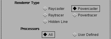
Processors
-
- Determines whether the renderer uses all available processors (All), or only a certain number of the available processors (User Defined). This parameter is only available when Renderer Type is Powercaster or Powertracer. If Processors is User Defined, the Num Processors parameter becomes available. The default setting is All.
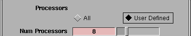
Num Processors
-
- The number or processors the renderer uses. This parameter is only available if Renderer Type is Powercaster or Powertracer, and Processors is User Defined. The valid/slider range is 1 to 32. The default setting is 8.
Host
-
- Determines whether rendering occurs on the local computer (Local) or on a remote computer (Remote). If Host is Remote, the Hostname and Location parameters become available. The default setting is Local.
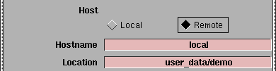
Hostname
-
- The name of the computer where rendering occurs. This parameter is only available if Host is Remote. You must have a user account on the remote computer, and the remote computer must have an Alias renderer installed. The default setting is local.
Location
-
- The path on the host computer (Hostname) where rendering occurs. This parameter is only available if Host is Remote. The default setting is the current project directory.
-
- The remote location must include any pix files used by shaders, or the remote computer must be NFS (Network File System) mounted to your local computer and your ALIAS_PIX_SEARCHPATH environment variable set accordingly. See Appendix B: NFS Overview on page 221 of the Release and Installation Notes, and ALIAS_PIX_SEARCHPATH (Rendering) on page 210 of the Release and Installation Notes.
Test Render
-
- Automatically names the rendered image file _username_computername_v9_test_render. If Test Render is ON, the Image Creation and Test Resolution parameters become available. The default setting is OFF.
-
- Because the renderer does not prompt you for an SDL file name, it creates a temporary SDL file and then automatically removes it once the render is complete.
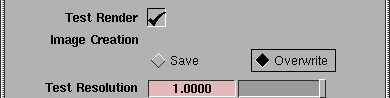
Image Creation
-
- Determines whether the test rendered image file is saved or overwritten by subsequent test renders. If Image Creation is Overwrite, the test rendered image file has the same name as the previous test rendered image file. If Image Creation is Save, the test rendered image file is given a unique name by adding a number suffix to (or incrementing the number suffix of) the previous test rendered image file name (for example, _username_computername_v9_test_render3). The default setting is Overwrite.
|
|
See X Resolution, Y Resolution
on page 414.
|
Test Resolution
-
- A scaling factor applied to the X Resolution and Y Resolution values in the Render Globals window. The slider range is 0 to 1. The default setting is 1.
Write SDL per frame
-
- Allows you to animate construction history or curve networks. If Write SDL per frame is ON, the renderer writes an SDL file with no animation in it, renders the SDL file, then advances the animation one frame and repeats this process until all frames have been rendered. If Write SDL per frame is ON, the Host and Test Render parameters become unavailable. The default setting is OFF.
-
- Note the following when using Write SDL per frame:
|
|
See Animation on page 397.
|
- Animation (in the Render Globals window) must be ON. If Animation is OFF, a warning message appears and the render continues as if Write SDL per frame was OFF.
- Make sure you are at the first frame of your animation before rendering.
- You must save the wire file before rendering it. The renderer uses this saved wire file to create the SDL files and image files.
- If DisplayTgls > Render Toggles > Render status is on, the progress bar indicates the percentage complete of the entire animation (rather than just one image file as in normal renders).
- Motion blur, Show Pix, Test Render, and Remote rendering do not work when Write SDL per frame is ON.
Rendering Options Window Buttons
Reset
-
- Resets all Rendering Options to their default settings.
Save
-
- Saves the current Rendering Options settings for use by all subsequent renders.
Exit
-
- Closes the Rendering Options window. The scene is not rendered, and any changes you have made to the Rendering Options are not saved.
Go
-
- Renders the scene using the current Rendering Options settings.
|
File > Export > SDL,
File > Edit SDL
|
SDL Files
|
|
|
|
|
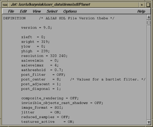
SDL is the Scene Description Language used by Alias. An SDL file is an ASCII text file that contains all the information necessary to render a scene, including models, shaders, lights, and animation. Because they are simple text files, you can edit, or even create, an SDL file "by hand". That is, you can create or edit a scene using a text editor and SDL commands. Usually, however, you will not need to directly edit SDL files. Instead, the interactive modeling program will automatically generate the SDL file for a scene and output it to the renderer.
There are, however, some cases where you may want to edit an SDL file:
- for absolute, mathematically control over scene elements such as models, animation paths, and shaders
- to modify a generated SDL file manually, or with another program
- to create new procedural effects using the general programming features of SDL.
By applying basic programming constructs to scene descriptions you can create useful and spectacular effects that would be tedious or impossible to create with the interactive modeler alone. You can also augment the dynamics and particle systems of the interactive modeler with the flexibility of the SDL programming language.
Once you have an SDL file describing a scene, you can then render it either within the interactive modeler, or using one of the stand-alone renderers (see Command Line Rendering on page 440). See the Alias Scene Description Language online documentation for more information.
To export an SDL file:
-
1
-
Select File > Export > SDL. The File Requestor appears.
-
2
-
Type the full path and file name for the SDL file in the File Requestor, or click Show List and select the file using the File Lister. If you select a file using the File Lister, the SDL file will overwrite that file.
-
3
-
Click Save SDL.
Note the following when exporting an SDL file:
- Delete all non-referenced shaders before exporting an SDL file, because all shaders, whether they are actually assigned to surfaces or not, are written out to the SDL file.
- When you export an SDL file, each perspective window will generate an image (or series of images) when the SDL file is rendered, because each perspective window has an associated camera.
-
The file name you use for the SDL file is also used within
the SDL file to specify the output image file name. For
example, if the SDL file is named Planet, then the camera
section of the SDL file will contain:
-
pix = "pix/Planet",
-
If there is a second perspective camera named camera2,
the SDL file will also contain:
-
pix ="pix/Planet_camera2",
-
If you have more than one perspective window, but only
want to render an image (or series of images) from one of
them, either edit the SDL file, or pick all objects, lights,
and only one camera, and then select File > Export > Active
as, and use that file to export an SDL file from.
To edit an SDL file:
-
1
-
Select File > Edit SDL. The File Requestor appears.
-
2
-
Type the full path and file name for the SDL file in the File Requestor, or click Show List and select the file using the File Lister.
-
3
-
Click Edit Text. The text editor opens with the SDL file displayed inside.
-
The default text editor is jot. You can change the default
editor by setting the ASCII Editor parameter in the Alias
Preferences window (see The Editor Options let you select an
alternate text editor to the default version of JOTASCII Editor
in the Basic Tools in Alias book). For more information on
using jot, select the Help menu in the top right corner of the
jot window.
-
If you entered a non-existent file name in the File
Requestor, the editor starts a new empty file. If you attempt
to edit a non-SDL file, the following message appears:
-
File type must be SDL.
Command Line Rendering
|
|
|
|
|
You can render an existing SDL file from a UNIX command line by using one of the stand-alone render programs: renderer, raytracer, powercaster, and powertracer. By rendering from a command line you can render a batch of several SDL files at the same time; the only limitation is the amount of swap space available. (For this reason the stand-alone renderers are also referred to as batch renderers.) You can also specify options during command line rendering which will override internal variables in the SDL file. This lets you change the behavior of the renderer without having to actually edit the SDL file.
Using the Stand-alone Renderers
The usage statement for renderer, raytracer, powercaster, and powertracer is:
renderer or raytracer or powercaster or powertracer
[-a#] [-b#] [-B#] [-c <quantized_output_file>] [-C
<color_map_filename>] [-d <filename>] [-e#] [-E#]
[-f <script>] [-h#] [-H] [-J] [-k] [-K#] [-m
<filename>] [-p <filename>] [-P] [-q#] [-Q#] [-r#]
[-R#] [-s#] [-S#] [-t#] [-T#] [-v] [-V] [-w#] [-W#]
[-x#] [-y#] [-Y#] [<filename>]
where:
|
|
-a#
| sets the anti-aliasing level (aalevel) to the integer #. aalevel is the maximum anti-aliasing level per pixel.
|
-b#
| sets the by frame number for animation sequences to the floating point number #.
|
-B#
| sets the by extension for animation sequences to the integer #.
|
-c <quantized_

output_file>
| outputs the quantized image to the file <quantized_output_file> after each frame.
|
-C color_map_

filename
| uses the SGI image format file <color_map_filename> as the color map to refer to for quantizing after each frame.*
|
-d <filename>
| uses <filename> as the depth file name.
|
-e#
| sets the ending frame number for animation sequences to the floating point number #.
|
-E#
| sets the size extension for animation sequences to the integer # where # indicates the number of 0 padding before the extension number. For example, -E 4 produces file extensions such as <file>.0001 indicating frame 1.
|
-f <script>
| invokes the program <script> after each frame.
|
-h#
| sets the image height for the partial image to be rendered to the integer # without changing the view port. However, this sub-region to be rendered always originates from the lower left hand corner of the image. The integer # moves the origin of this window around the view port.
|
-H
| displays the on-line help.
|
-J
| creates a depth file called `timing' representing time per pixel.
|
-k
| keeps depth maps in memory after reading them once.**
|
-K#
| turns depth maps on disk usage to #. 0 is OFF. Any number other than zero is ON. ***
|
-m <filename>
| produces a matte file and uses <filename> as the file name.
|
-n#
| sets, to the integer #, the number of processors to render on. This option is only available with powertracer and powercaster.
|
-p <filename>
| uses <filename> as the pix file name.
|
-P
| preserves the non-glowed image unless DOF or Quantize are on. This option allows you to save both a glowed and non-glowed image on disk. The non-glowed image will have the same name as the glowed image, but will have the suffix .ng.
|
-q#
| sets the quiet flag to #. # can be 0, 1, or 2.
|
-Q#
| sets the resolution in the X direction and the view port to the integer #. This option is useful for overriding the resolution specified in a given SDL file. For example, it is useful for switching between rendering NTSC and 1/4 NTSC for a quick preview render.
|
-r#
| sets the aspect ratio to the floating point number #.
|
-R#
| sets the resolution in the Y direction and the view port to the integer #. This option is useful for overriding the resolution specified in a given SDL file. For example, it is useful for switching between rendering NTSC and 1/4 NTSC for a quick preview render.
|
-s#
| sets the starting frame number for animation sequences to the floating point number #.
|
-S#
| sets the start extension for animation sequences to the integer #.
|
-t#
| sets the aathreshold to the integer #. aathreshold is the anti-aliasing threshold value that adaptively super-samples pixels based on color difference. The higher the value, the more sensitive the super-sampling is to color difference.
|
-T#
| sets the number of Y pixels in a tile to the integer #. A tile is a row of pixels to be rendered together. The main reason to use this option is to reduce the amount of memory used by lowering the Y value. This controls the tile size the image is broken up into for rendering and has no effect on the final image or its resolution.
The more tiles, the better the load balancing, but the process may be slow. The default tile size is 15 scanlines. You may want to increase the tile size for images with over 1K of vertical (Y) resolution, to a value between 40 and 60. For images with less than 500 pixels vertical (Y) resolution, decrease the tile size to a value between 10 and 25
|
-v
| render normally outside of viewport region
|
-V
| render image with hidden lines
|
-w#
| sets the image width for the partial image to be rendered to the integer # without changing the view port. However, this sub-region to be rendered always originates from the lower left hand corner of the image. The integer # moves the origin of this window around the view port.
|
-W#
| sets the ylow for backgrounds to #. The ylow and yhigh define the region of the rendering, specified in pixels, where the background should appear.
|
-x#
| sets the xleft to the integer #. xleft is the left corner of the partial image to be rendered.
|
-y#
| sets the ylow to the integer #. ylow is the left corner of the partial image to be rendered.
|
-Y#
| sets the yhigh for backgrounds to #. The ylow and yhigh define the region of the rendering, specified in pixels, where the background should appear.
|
filename
| sets the SDL file name to a specific file name. If no file name is specified, standard input is used.
|
|
|
* If required, the renderer quantizes images after rendering them. The option -C allows a previously generated color table to be used for quantizing images. However, aquant quantizes images much more quickly.
** Generally, when a depth_input file is specified for a shadowing spotlight, it is read every frame. -k forces the renderer to read the shadow map only once during the first frame of rendering.
*** Rather than editing your SDL files to add depth_input or depth_output commands to shadowing spotlights, this command line option may be used. When set to a non-zero value (for example -K 1), the renderer automatically creates depth output files named after the spotlights in your current directory, or if these files already exist, they are used.
Using any of the above options overrides any equivalent SDL keyword settings in the SDL file.
See renderer/raytracer in the Alias Stand-alone Utilities Guide online documentation for more information on the stand-alone renderers.
To render a scene from the UNIX command line:
-
1
-
Export the scene as an SDL file (see SDL Files on page 437) by selecting File > Export > SDL and entering a file name in the File Requestor. For example, type:
-
/usr/u/kozyniak/user_data/demo/sdl/
filename
-
2
-
Open a UNIX shell (for example, by selecting Utilities > UNIX shell) and change the directory to that of the current project (that is, one directory above the SDL file). For example, type:
-
cd /usr/u/kozyniak/user_data/demo
-
You must be in the project directory (that is, one directory
above the SDL file) when using the stand-alone renderers.
-
3
-
To raycast the scene, type:
-
renderer sdl/filename
-
To raytrace the scene, type:
-
raytracer sdl/filename
-
To powercast the scene, type:
-
powercaster sdl/filename
-
To powertrace the scene, type:
-
powertracer sdl/filename
-
There are several options that you can use with the stand-
alone renderers (see Using the Stand-alone Renderers on
page 440).
-
The renderer displays information on the elapsed time for
each frame and for the total render. For example:
Alias Renderer, Version 8.5.1 (/usr/alias/bin/
renderer.i6.4k)

Elapsed time for the parse (hh:mm:ss): 00:00:00

    Completed pix/Nebula file

    Memory(kb): 3099

Elapsed time for the Raycast (hh:mm:ss): 00:00:15

Elapsed time for the Frame Render (hh:mm:ss):
00:00:15

Elapsed time for the Total Render (hh:mm:ss):
00:00:15
|


