|
|
4
|
Working in the Action Window
|
|
In This Section:
|
Animation > Action
window
|
The Action Window
|
|
|
|
|
The Action window lets you see, create, and edit keyframes and animation curves, as well as cut and paste animation between different animation parameters. The Action Window also lets you create and edit expressions and attach these expressions to animation parameters.
Overview
Select Animation > Action window to open the Action Window. The Action Window has three components:
- the Action Lister on page 140
- the Action Graph Editor on page 146
- the Action Timeview on page 147
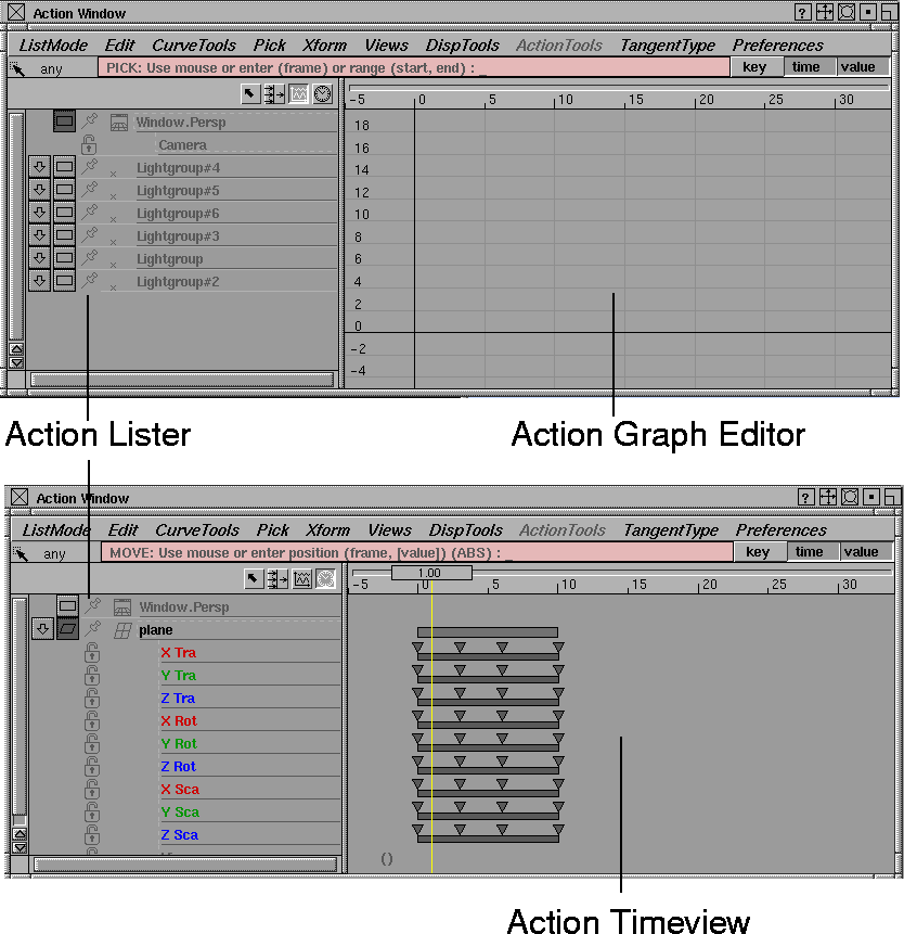
The Action Lister is always displayed on the left side of the Action Window.
|
|

|
On the right side, you can display either the graph editor or the timeview. Use one of the icons in the lister title bar to switch between these two views.
The Action Window also has its own set of pull-down menus. See Action Window menus on Action Window Menus on page 149 for information.
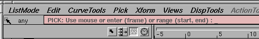
There is a prompt line below the menus. It displays error message information and prompts you for input that is required when you select certain menus. When the prompt line is dark pink and the cursor is not in the Action Window, you know that the window is not active. The cursor must be in the Action Window in order for keyboard input to be recognized. The prompt line also contains snap toggles (see page 139) that help you constrain movement.
Notes
- Some menus or menu functions are not applicable in some situations. For example, if the timeview display is active, you cannot use the Action Window Pick > Tangents function, since tangents are only visible with the graph editor. Unavailable functions appear in light gray text.
- The minimum time that can be displayed in the Action Window is -160,000.00. The maximum is +160,000.00.
Action Window Snap Toggles
|
|

|
key toggle
-
- The key toggle is located to the right of the prompt line. When toggled on, the time slider bar is snapped to keyframes. When moving keyframes, they are snapped to times and/or values of other keyframes as follows:
- If you use the left mouse button, keyframes are snapped to the time and value of other keyframes.
- If you use the middle mouse button, keyframes are snapped to the time of other keyframes.
- If you use the right mouse button, keyframes are snapped to the value of other keyframes.
|
|

|
time toggle
-
- The time toggle is located to the right of the key toggle. Use this toggle to constrain the movement when keyframes or the current time slider bar are moved.
-
- When time is toggled on, the time slider bar and the time of keyframes snap to integer values. When toggled off, you can move selected keyframes and/or the slider time bar to any time.
|
|

|
value toggle
-
- The value toggle is located to the right of the time snap toggle. This toggle is used to constrain the movement when keyframes are moved.
-
- When value is toggled on, the value of keyframes snap to integer values. When toggled off, you can move selected keyframes to any value.
|
|
|
time slider
-
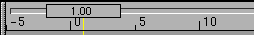
- The graph editor and timeview both have a time slider. This is the vertical bar that crosses the window with a box at the top that contains the current time. The time slider bar slides along a horizontal rail. You can change the current time by clicking anywhere in that rail and dragging left or right. When you drag to a new current time, notice that all animatable objects are updated with their channels evaluated at this new time.
|
|
This is similar to choosing
Anim > View frame and
selecting a new current time
at which to view the world.
|
-
- You can also double-click in the time slider box to change the current time. When the box turns pink, with the existing time on a grey background, type the new current time. A single click in the time slider box updates the animated world. This is useful if you have changed any keyframe positions, as these changes are not automatically reflected in the animated world.
Action Lister
The Action Lister lists items with their channels and is always displayed on the left hand side of the Action window. The contents of the lister depends on the settings of the List Mode menu (see page 149). Objects and channels that have an animation associated with them are displayed in a dark color, while entries without an animation appear in a lighter color. Parameters that have an expression attached to them also appear in a dark color, with a pair of brackets () next to the parameter name (if Disp Tools > Show curve names is enabled in the Action Window, the expression will appear within the brackets).
|
|
Use the Action window's
Disp Tools > Tgl Curve
Names on page 166.
|
Channels animated by a single action may also have the name of the action curve displayed next to the parameter name.
Action Lister buttons and icons
|
|

|
Model-Pick button
-
- Takes the objects currently selected in the Action Window lister and makes them active in the modeling windows.
|
|

|
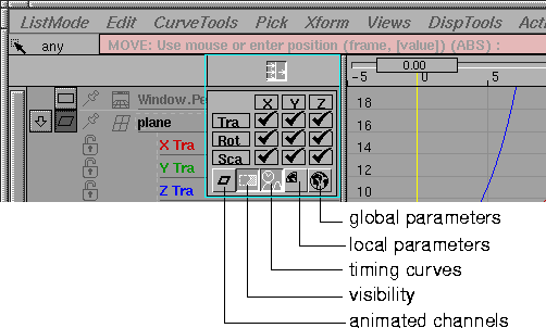
Param Filter button
-
- Opens the filter control panel that lets you select which channels are displayed in the action lister.
|
|
To open and close the filter
control panel, click the
Param Filter button. While
the filter control panel is
open, you cannot perform
any other function in Alias.
|
Filter Control panel
-
- The filter control panel is geared specifically towards DAG node channels. For other types of objects, you can choose between the local and global settings in the Param Control window
(see Animation > Param control).
-
- A DAG node has ten animatable parameters, but the most commonly used ones are the X, Y, and Z translate, rotate and scale parameters. The 3X3 grid in the parameter control filter allows you to quickly turn the display of these nine parameters on and off, reducing the amount of data in the action lister.
-
- To turn a parameter on or off, click in the appropriate box. For example, clicking in the second column of the first row turns off the Y translate parameter. Clicking in the box again turns it on again. You can toggle all the translate, rotate or scale parameters at once by clicking in the Tra, Rot, or Sca buttons. Similarly, you can toggle all the X, Y, or Z parameters by clicking on the X, Y, or Z buttons respectively.
-
- Below the 3 XYZ toggles are five more buttons:
|
|

|
- The first button is a filter for animated channels. If this button is toggled on, only the channels with animation information in them will be displayed in the lister.
|
|

|
- The second button, Visibility, is a filter for the tenth DAG node animation parameter. It is represented as a DAG node SBD box with a section removed from it.
|
|

|
- The third button is obsolete. (It duplicated the display of timewarps. Because there is no longer the need for filtering them, the functionality of this button has been removed.)
|
|

|
- The fourth and fifth buttons in the filter panel represent local and global parameter filters, and are represented by a quarter and a full globe respectively. These buttons control which animation parameters are filtered out of the action lister for all animatable items other than DAG nodes.
-
If neither of the fourth and fifth buttons is selected, then all
animation parameters for non-DAG node items are listed. If
only the local parameter button is selected, then only
those animation parameters are listed that correspond to
those selected in the item's local parameter control.
-
If the global parameter button is selected, then only those
animation parameters selected in the global parameter
control are used.
|
|
See Animation > Param
control on page 19 for more
details.
|
-
When you have finished toggling buttons on and off in the
param filter panel, click on the param filter button again to
close the panel. The Action Lister updates to display the
selected parameters.
|
|

|
graph editor button
-
- The graph editor button activates the graph editor (which appears to the right of the action lister). The graph editor lets you view and change action curves for any channel.
|
|

|
timeview button
-
- The timeview button activates the timeview (which appears to the right of the action lister, replacing the graph editor). The timeview lets you view overall animation timing for any channel, and create and edit expressions and attach them to animation parameters.
Selecting in the Lister
For various operations in the action lister, you must select elements in the lister before selecting a function.
- To select an action lister element, click on it.
- To select more than one element at a time, click on the first one, drag the cursor up or down to the last element, and then release the mouse. All items between the first and last elements are selected.
- To add or remove an element from the currently selected list, hold down Shift while clicking on the element. If it is already selected, it will be deselected. If it is not already selected, it will be selected.
If you have selected more than one item in the list, you can use the expand item and expand animation buttons to expand all selected items at once. For example, if you select three out of five animated items, and then click on the expand animation button for one of the selected items, all three selected items will have their animation parameters added to the list. (For an in-depth explanation of these buttons, see the next section.)
Changing names in the lister
|
|
See Animation > Param
control on page 19 for a
complete list of all animation
parameters for all types of
animatable items.
|
You can change the name of most entries in the action lister by double-clicking on the entry that you want to change. The field turns light pink, indicating that you can type the new name. Press Esc to clear the field of the current name, and type the new name. If you make a mistake, use the Backspace key. Any action curve can be renamed, as well as most animatable items, such as DAG nodes and shaders.
>
|
Note:
|
You cannot rename CVs or polyset vertices, since these
items get their names from the name of the DAG node above
them. You also cannot rename animation parameter names
since these are names used throughout Alias to identify the
parameter.
|
|
|
|
object type icon
-
- The icon to the left of each object's name shows the object type. For example, a DAG node above a surface has a surface icon, a DAG node above another DAG node has a DAG node icon, and a camera has a camera icon.
|
|

|
expand item button
-
- If an object has any descendants, it has this button next to it. Click on this button to add the object's descendants to the lister. The new sub-objects are indented with respect to the first object to show the object's hierarchy. For example, if a DAG node above a surface is in the lister, it has an expand item button. When this button is pressed, all the surface CVs are listed with their names indented below that of the surface DAG node.
-
- When an object is expanded, click on this same button to compress its items- that is, to remove its descendants from the Action Lister.
-
- If you hold the Shift key while clicking on the expand item button, the item expands to its children, each of the children expand to their children, and this continues until all items below the original item are expanded.
>
|
Note:
|
Using the Shift key to expand does not expand leaf
geometry DAG nodes to their CVs. This restriction is made
so that you can expand DAG node hierarchies quickly
without having to list the potentially large number of CVs
that belong to curves or surfaces.
|
|
|

|
expand animation button
-
- If the item in the lister is animatable, it has an expand animation button next to its name (between the expand item button and the item type icon). Click on this button to add the item's animation parameters to the lister. What appears in the lister depends on the filter control panel settings. See Filter Control panel on page 141.
-
- When an item is expanded to show its animation parameters, press the expand animation button again to compress the items and remove the animation parameters from the lister.
|
|
See also Introduction to
Inverse Kinematics on
page 244 for details about
spline handles and rotation
order.
|
>
|
Note:
|
If the animated object is an IK handle, its parameter names
may come with special notes. For example, if the object is a
single-chain IK handle, its X Rot may be shown as X
Rot[PoleX], Y Rot as Y Rot[Plane], and Z Rot as Z
Rot[PoleY]. When you change the rotation order
for the
single-chain handle, the notes are updated accordingly.
|
|
|
For other examples, the X Rot parameter becomes X
Rot[Roll], and the X Tra becomes X Tra[Pos] if it is a spline
root handle. The X Rot becomes X Rot[Twist] if it is a spline
master handle.
|
|
|

|
pin object button
-
- If an object is pinned, it will remain visible in the Action Window lister even if it becomes unpicked in the modeling window or its parent object in the lister is compressed.
|
|

|
expand channel button
-
- If an animation parameter is animated, it has a channel associated with it. If the channel has more than one action associated with it (for instance, it has at least one timing curve applied to its base action), then it has an expand channel button next to its name.Press this button to add the channel's action curves to the lister.
-
- The new actions are indented with respect to the channel. Actions are listed in the order in which they are applied, with the base action being listed first.
-
- When a channel is expanded, click on its expand channel button to compress- that is, to remove the actions of the channel from the action lister.
padlock
|
|

|
-
- If a channel is padlocked, it will remain visible in the Action Window lister, even if the channel filters or parameter controls are changed such that the channel would otherwise be removed from the lister.
>
|
Note:
|
Padlocked channels are still removed from the lister when
the object's channel list is compressed.
|
Action Graph Editor
|
|
View the graph editor
with this icon.
|
Use the graph editor to create and modify actions. There are also a few operations that you can apply to channels.
The curves that are displayed in the graph editor reflect what is currently in the action lister. For example, if an item has three parameters that are animated each by a single curve channel, then three actions will be displayed in the graph editor.
If a channel has two or more actions on it (a base action and timing curves, for example, which were created using Set motion), the channel appears in the lister with an expand channel button. When you click this button, the channel's animation curves are added to the lister and to the graph editor. If the channel is not expanded, only the resulting animation curve on the channel will be displayed in the graph editor. The resulting curve (result curve) is the final evaluation of the channel with all of its actions. Result curves will always be displayed as dashed lines because they are not editable. You can toggle their display on or off by selecting Tgl result curves from the Disp Tools menu in the Action Window.
You can pick channels and animation curves in the graph editor by selecting the name of the animation parameter in the action lister.
- If the curves are picked using Pick > Curve, their curve names are highlighted in the action lister.
- If a keyframe of a curve is picked in the graph editor, a yellow X is placed to the left of the curve name in the action lister, to indicate that at least one keyframe on that curve is picked.
- If a tangent of a curve is picked in the graph editor, a green arrow is placed to the left of the curve name in the action lister, to indicate that at least one tangent on that curve is picked. The direction of the arrow indicates whether an in or out tangent (or both) has been picked.
Action Timeview
|
|
View the timeview with this
icon:

|
The timeview is an alternate way of viewing actions and channels. You see only timing duration without the animation curves that are displayed in the graph editor. The timeview
is useful if you are satisfied with the motion in your animation, but want to adjust the timing. You can edit individual actions, single channels of an animatable item, or channels for the whole animatable item. This view can also be useful for coordinating the movement of objects in your scene.
- A parameter curve action is represented by a time bar whose length is defined by the first and last keyframes of the action. The keyframes are represented by little triangles placed at their appropriate times.
- A motion path action simply has a name next to it, which is the name of its associated 3D NURBS modeling curve. To edit a motion path action, edit the NURBS curve in the modeling windows.
- The timeview contains summary bars next to animated items. A summary bar represents the range over which the item is animated by all of its channels. If the summary bar can be edited (that is, you can move it or scale it in time), it has a solid outline. If it can't be edited (that is, at least one of the item's channels is not editable), the summary bar has a dashed outline. Summary bars can be edited if and only if all of their channels can be edited.
-
The summary bars of channels can be edited if the channel
uses only one action, and this action is a parameter curve.
If a channel can't be edited, try expanding it and editing
its individual parameter curves.
- You can create, view, and edit expressions in the timeview. Any animation parameter which is not currently animated may have an expression attached to it (use Edit > Clear to remove animation from an animation parameter).
-
Double-clicking in the timeview next to the desired
animation parameter allows an expression to be entered
(you can also use Edit > Edit expression to use the external
editor defined in Alias Preferences to edit or create an
expression).
Action Window Menus
|
|
|
|
|
|
|

|
ListMode Menu
The List Mode menu lets you specify which objects are displayed in the action lister.
Picked
-
- Lists all the modeling objects that are picked.
All
-
- Lists all root level items in the universe.
Picking Items
- A DAG node, CV, camera, or image plane is considered by the Action Window to be picked in the modeling windows.
- A shader, texture, light or environment map is considered picked if it is picked in the multi-lister. (Use Windows > Multi-lister. See Rendering in Alias.)
- A perspective window is picked if it is current.
- The Universe is picked if Pose Animation is ON in the Playback Options window (see Animation > Playback options > Animation Options on page 85).
For items that appear in the SBD window, only the root level DAG nodes are listed. The hierarchical items below the DAG node can then be expanded using the expand item button.
Other types of items that are listed in this mode include the Universe and all animatable perspective windows.
|
|
|
Edit Menu
The Edit menu lets you perform operations on items selected in the action lister.
Keyframe Edit
-
- Opens up the Keyframe Stats window which can be used to edit the frame, value, and tangents of individual keyframes. See the description of the Keyframe Stats window on page 153 for more details.
Edit Expression
-
- Opens whichever editor has been defined in Alias Preferences as the ASCII editor to create or edit an expression for the currently selected animation parameter. See Using Expressions on page 175 for more information.
Cut
-
- Deletes selected items.
-
- To remove the animation from a parameter, for example, select the parameter in the action lister and select Cut to delete the channel. Note that only the animation is deleted; the parameter itself still remains in the lister, but is now shown in a dim color to indicate its lack of animation.
-
- You can also delete keyframes or individual actions using Cut. If you cut something by accident, use Undo to restore it.
-
- If you cut only one channel or action curve, the animation is placed on the clipboard (replacing anything that may have been there already) so you can paste it later onto an unanimated parameter (see Paste and Paste Instance below).
Copy
-
- Copies one channel or action curve to the clipboard (replacing anything that may have been there already) so that you can paste it later (see Paste and Paste Instance).
-
- If a tangent is picked, both the tangent angle and tangent type are copied.
Paste
-
- Pastes a channel or action curve onto an animation parameter that has no animation currently attached to it.
|
Tip:
|
If tangent information has been copied to the clipboard,
Paste can be used to alter the tangent angles and tangent
types of any picked tangents.
|
|
|
The channel or action that is
pasted onto the animation
parameter is the one that is
currently on the clipboard.
Actions and channels are
placed on the clipboard after
a Copy or Cut operation.
|
Copy Segment
-
- Copies a segment of an animation curve onto the clipboard.
-
- Use Paste Segment to insert this segment onto another curve. To copy a segment, pick the keyframes from a curve. The segment is defined as the part of the curve between the first and last keyframes picked on the curve.
Paste Segment and Paste Segment With Offset
-
- Inserts a curve segment from the clipboard into an existing curve.
-
- Paste Segment With Offset will offset the values of the pasted segment that is, raise or lower the segment) so that its first keyframe sits precisely on the selected curve at the specified time. Paste Segment (without offset) will leave all of the values in the pasted segment untouched.
-
- To Use Paste Segment and Paste Segment With Offset:
-
1
-
Select the curve onto which you want to paste the segment.
-
2
-
Click on the curve and drag along the curve to the location at which the segment should be inserted.
-
Alternately, you can use the keyboard to specify where the
curve segment should be pasted. When you select Paste
Segment or Paste Segment With Offset, the system prompts:
-
Click or drag on curve to define insert
location (time, [repeat], [gap]):
-
Type the time at which the first keyframe of the segment
should be placed. Optionally, type the number of copies of
the segment to paste (this is the Repeat option). The repeat
is 1 by default. If you enter a repeat of more than 1, you can
optionally enter a gap in time to be inserted between the
segments. The default is 0.
>
|
Note:
|
To paste a segment onto an unanimated parameter, you
must use keyboard input.
|
Clear
-
- Deletes selected items without placing them on the clipboard.
|
|
If you clear something by
accident, use Undo to restore
it.
|
-
- To remove animation from a parameter, for example, select the parameter in the action lister, then select Clear to delete the channel.
>
|
Note:
|
Only the animation is deleted. The parameter itself still
remains in the lister, but is now shown in a dim color to
reflect its lack of an animation.
|
Paste Instance
-
- Similar to a paste operation, except that the newly animated parameter reuses the animation curve on the clipboard instead of making a copy.
-
- To Use Paste Instance:
-
1
-
Select a channel from one object and invoke Copy.
-
2
-
Select an unanimated parameter from the same or a different object, and invoke Paste Instance.
-
The newly animated parameter and the original channel
share the same action curve(s). Now if you edit the action,
the animation for both channels is affected.
Show Instance
-
- Shows all the channels that are using a particular action curve.
-
- Sometimes an action curve can be used by more than one channel. For example, if you create motion path animation (using Anim Tools > Set motion) or a new timewarp (using Animation > Time Warps > New time warp), then the animation curve(s) created are shared by more than one channel. To share an existing action with more than one channel, use Paste Instance.
-
- To see all the channels that are using a particular action curve, select the action and choose Show Instance from the Edit menu.
-
- A utility lister appears listing the name of the action. Below the action is listed, the names of the objects and their animation parameter which use the action.
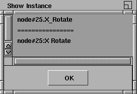
-
- You must close the utility lister by clicking OK before proceeding with any other operation in Alias.
Undo
-
- Undoes previous operations on keyframes, tangents, and an action itself (such as Xform, Tangent Type and Edit operations).
-
- Undo keeps a history of transformations, so that if you repeat Undo, it will undo further back in the history.
Redo
-
- Recreates what was undone by Undo.
-
- You can use Redo to reverse the last operation from Undo. You can redo as many operations as you undid with Undo.
>
|
Note:
|
Delete operations which are performed outside the Action
Window (for example, Delete > Del active or Delete > Del
channels) will delete the undo history in the Action Window.
|
Viewing and Editing Keyframe Stats
Select Keyframe Edit to open the Keyframe stats window, which lets you view and edit frame, value and tangent information for one or more keyframes, one keyframe at a time.
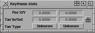
Once the window is opened, pick a keyframe in the Action window. You can then unpick that keyframe and pick another one, and the information in the stats window is updated for the new picked keyframe.
The parameters in the keyframe stats window are the following:
Pos' X/Y
-
- The current position of the keyframe. The first number is the frame time of the keyframe, and the second number is the value of the keyframe. You can change the position of the keyframe by clicking on a number and entering a new number.
>
|
Note:
|
You will not be able to enter a time that is outside the
segment in which the keyframe is contained.
|
Tan' In/Out
-
- The angles of the in- and out-tangents on the keyframe. The values must be between -90.0 and 90.0. If you change the value of either of these tangents, the tangent type for that tangent becomes fixed. This ensures that the new tangent value you assigned to the keyframe retains that value.
|
|

|
Tangent Lock Button
-
- Next to the tangent values is a tangent lock button. Clicking this button will lock in the current angle between the in and out-tangents, so that if you modify one of them, the other will automatically be modified by a compensating amount.
-
- For example, if the in-tangent is 10 degrees and the out-tangent is 30 degrees, then the angle between them is (90 - 30) + (90 - 10) = 140 degrees. It you turn on the tangent lock and change the out-tangent value to -20 degrees (a decrease of 30), then the in-tangent value will change to 60 degrees (an increase of 30) thereby maintaining the 140 degree angle between them.
>
|
Note:
|
The tangent lock button only works for changes in the
keyframe stats window. To maintain a tangent relationship
when changing tangents using Xform > Move, use the right
mouse button.
|
|
|
For more information on
tangent types, see the
description of the Tangent
Type menu on page 170.
|
Tan' Type
-
- Shows the current type of the in- and out-tangents. The tangent type controls how tangents are recomputed when a keyframe is moved, or when keyframes are added or deleted next to the keyframe. Click down on the currently displayed tangent type to use a menu to select a different tangent type. (The current tangent type is highlighted in the menu.)
Notes on Selecting Multiple Keyframes
When you have the keyframe stats window open, you can also select multiple keyframes. If any of the position or tangent values are the same for all picked keyframes, the corresponding value will be shown in black.
If the values are not all the same, the value in the keyframe stats window will be gray. If you click on this value and enter a new value, and then all picked keyframes will assume this same value.
For example, if you pick two keyframes, one with a value of 5 and the other has a value of 10, then the keyframe stats will show the value of one of the keyframes in gray, indicating that not all picked keyframes have the same value. If you click on this grayed value and type in 7, now both keyframes will be given a value of 7 (and it will be displayed in black).
|
|
Tangent angles and tangent
types can also be copied
from one keyframe to
another using Edit > Copy
and Edit > Paste.
|
If multiple keyframes are picked and they all have the same tangent type, then this tangent type will be displayed. If not all keyframes have the same tangent type, then the Tan' Type parameter will say Unknown. You can click on an Unknown tangent type and select another tangent type; then all keyframes will assume this same tangent type.
|
|
|
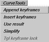
CurveTools Menu
Use the CurveTools menu to create and modify action curves.
Append keyframes
-
- Adds keyframes to an existing action, or creates a new action for a parameter that is not currently animated.
-
To use Append keyframes:
-
1
-
Select an unanimated parameter, or a parameter curve action.
-
2
-
Click in the graph editor at the place you would like the new keyframe created, or use the keyboard to specify the frame time and value of the new keyframe.
-
The tangent types of the new keyframe depend on the
current tangent type mode. See the Tangent Type menu on
page 170 for more details.
Insert keyframes
-
- Adds keyframes to an existing action.
-
To use Insert keyframes:
-
1
-
Select the action in the action lister, or pick the action in the graph editor (using Pick > Curve).
-
2
-
Select CurveTools > Insert keyframes and click and drag to the frame at which you would like to insert the keyframe.
-
The keyframe will be inserted using the same value as the
action originally had at that frame. The tangents of the
new keyframe will be adjusted to preserve the original
shape of the action.
>
|
Note:
|
Insert keyframes will only add keyframes to a curve
between its first and last keyframes. If you wish to extend an
existing curve before its first keyframe or beyond its last
one, then use Append keyframes.
|
Use result
-
- Compresses all actions applied to a channel into one parameter curve that maintains the same shape as the original animation of the channel.
-
- This function is very useful if a channel is animated with several timewarps, and you want to edit the channel as a whole, instead of as individual actions.
-
To use Use result:
|
|
See Anim > Set motion on
page 37 and Animation >
Time Warps > New time warp
on page 426.
|
-
1
-
Animate an item along a motion path or apply one or more timewarps to a channel. The channels with the motion path and/or timewarps appear as dashed lines because they can't be edited. Compressing these non-editable channels makes them editable, since the channel then uses only a single parameter curve action.
-
2
-
Select the non-editable channels that you want to compress.
-
3
-
Select CurveTools > Use result. You are prompted to enter a start, end, and by value at which to sample the channel.
|
|
If you do not specify start,
end, or by, defaults are used.
The default start
and end
values are the range of the
channel being compressed.
The default by value is 1.
|
- The start and end values represent the range over which the new parameter curve is defined.
- The by value is the frequency with which new keyframes are created.
-
For example, if you enter start, end, and by values of 0, 10,
and 2 respectively, a parameter curve action is created
with six keyframes at times 0, 2, 4, 6, 8, and 10.
-
Using a large by value is faster, but may give an inaccurate
result curve, especially if the animation performs many
sudden and dramatic changes in value. If this occurs, use
Edit > Undo to restore the original curves and them try
again with a smaller by value.
Caution! If a channel has one or more timewarps, the range of the channel is not well-defined. Specify explicitly the start and end values for the channel, rather than relying on the default values.
Simplify
-
- Simplifies a curve by reducing the number of keyframes in it while still preserving the shape of the curve within a tolerance.
-
- When you select Simplify, the system prompts:
-
Select actions to simplify. Enter range &
tolerance ([start], [end], [by], [0.050]):
-
If you simply press Enter, the selected actions are
simplified with default tolerances and ranges.
|
|
The default values for start
and end are the complete
range of the actions selected.
The default by value is 1, and
the default tolerance value is
0.05.
|
-
- Alternately:
- Type the start and end at the keyboard to specify the frame range in which to simplify the actions.
- Use the by option to simplify the frame tolerance. The simplified action will be equivalent to the original action (within a value tolerance) at this frame tolerance.
- The fourth number to enter is the value tolerance. This specifies by how much each frame at the frame tolerance is allowed to differ in the simplified action from the original action.
-
- When you select Simplify, you can either press Enter, type just one number, or four numbers. If you type one number, this number is used as the value tolerance. If you type four numbers, these numbers are interpreted to be the start, end, by, and value tolerance respectively.
Tgl keyframe lock
-
- Toggles the lock state of a keyframe.
-
- If a keyframe is locked, it cannot change location or value when you perform an Xform > Move. This is useful if you want to ensure that a specific keyframe happens at a specific time, and you want to avoid accidentally moving it. Locked keyframes are displayed as solid squares in both the graph editor and the timeview.
|
|
|
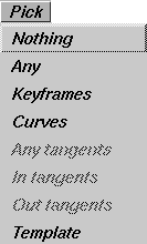
Pick Menu
Use the Pick menu to pick various items in the action editor. Pick is similar to the standard Alias Pick, but it operates on actions, channels, and keyframes. You can pick an item by clicking on it. To pick multiple items, click and drag. In the action lister this will pick several adjacent items. In the graph and time views it will drag out a pick box; everything inside the pick box is made active when you release the mouse button.
|
|
The graph editor Pick
functions have the added
capability of picking while
you are in other functions. If
you hold the Shift key, you
are automatically in Pick
mode no matter which menu
item is current.
|
You can also pick curves by typing the curve name in the prompt line. Wildcard characters (such as *,?) can be used to select curves with similar names. For example, sphere.*Translate
will pick all the sphere's Translate animation curves. Use DispTools > Show curve names to display the names of the curves.
Nothing
-
- Unpicks anything that is active in the Graph Editor, Action Lister, or Timeview.
Any
-
- Picks whatever is contained inside the pick box. It picks channels or any component of an action: keyframes, tangents and/or actions.
-
- Since keyframes, tangents, and actions cannot be picked at the same time, a pick priority defines what is picked if all three of these action components are inside the pick box: keyframes, then tangents, then the action itself.
Keyframes
-
- Picks the keyframes of an action.
-
- You can pick keyframes in a certain time range by typing the first and last time of the range at the keyboard. Be sure that your cursor is in the Action Window so that keyboard input goes to the Action Window. Keyframe display can be toggled on or off using DispTools > Show keyframes.
Curves
-
- Picks actions or channels. If a curve is picked in the graph editor, it is also selected in the action lister.
Any tangents
-
- Picks a keyframe's in-tangents and/or out-tangents.
In tangents
-
- Picks only the in-tangents of keyframes. The in-tangent is the tangent entering the keyframe (from the left).
Out tangents
-
- Picks only the out-tangents of keyframes. The out-tangent is the tangent where the curve leaves the keyframe.
Template
-
- Picks templated curves. A curve can be templated using DispTools > Tgl template.
If the Pick type is set to Keyframes, selecting an action (or a single-action channel) in the lister will toggle the pickstate of every keyframe on that action, meaning that unpicked keyframes will become picked, and vice-versa.
Similarly, if the Pick type is set to Any Tangents, In Tangents, or Out Tangents, then the pick states of all the tangents on the curve, or just the in- or out-tangents respectively, will be toggled.
Using keyboard input to move between keyframes and tangents
By holding down the Ctrl key and using the arrow keys, you can "pick-walk" through keyframes and tangents.
Pick-walking lets you pick a keyframe or tangent and then, with the use of the keyboard arrows, go on to pick another while unpicking its predecessor.
Ctrl-left arrow walks to the next keyframe or tangent on the same action curve.
Ctrl-right arrow walks to the previous keyframe or tangent on the same action curve.
Ctrl-up arrow walks to the keyframe or tangent which is at the same time in the action curve above the current one.
Ctrl-down arrow walks to the keyframe or tangent which is at the same time in the action curve below the current one.
Notes on Pick-Walking
- Since curves may cross several times, the terms above and below are somewhat arbitrary. If you walk up you may actually end up moving to the curve which is visually below the current one at that point in the graph. In reality, walking down traverses the action curves in the order in which they were created while walking up traverses them in the reverse direction.
- If you walk through to the end or start keyframe, the next picked will be the start or end keyframe respectively.
- If an in-tangent is picked, the next picked will be an in-tangent, as well.
- If an entire action is picked, using Ctrl-right arrow unpicks the action and picks the first keyframe or tangent; Ctrl-left arrow picks the last keyframe or tangent of the action.
- Multiple keyframes and tangents can be walked simultaneously.
|
|
|
Xform Menu
The Xform menu performs operations on items selected in the action lister, timeview, or graph editor.
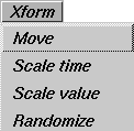
Move
-
- Lets you move keyframes, tangents, or the whole curve.
|
|
|
-
To use Move, select any number of components using Pick
and then select Move. Drag the cursor in the graph editor
window. The picked objects follow the cursor.
When moving keyframes and curves:
- the left mouse button moves objects in both the horizontal and vertical directions.
- the middle mouse button constrains movement horizontally.
- the right mouse button constrains movement vertically.
When moving tangents...
- the left mouse button moves without constraints. Note however, that tangents are always constrained such that the in-tangent stays to the left of the keyframe, and the out-tangent stays to the right of the keyframe.
- the middle mouse button locks the in- and out-tangents of a keyframe so they remain 180 degrees apart (that is, in a straight line). This ensures that the curve is smooth through the keyframe.
- the right mouse button locks the in- and out-tangents of a keyframe so they maintain the current angle between them.
Normally, when moving tangents, horizontal motion of the mouse is ignored and the tangents move proportionally to the vertical motion of the mouse. So, if the mouse moves one quarter of the way up the Action Window, all of the selected tangents will move up by 45 degrees, which is one quarter of their total range of movement.
If you hold down the Ctrl key while moving tangents, instead of proportional movement you get direct movement, where the tangents point directly at the current position of the selection arrow:
- the left mouse button causes all active tangents to immediately change position so that they point directly at the selection arrow. Note if a tangent is on the opposite side of its keyframe from the selection arrow, it cannot point directly at the pointer and instead is pinned to point straight up if the pointer is higher than the keyframe, or straight down if the pointer is lower than the keyframe. For this reason it is typically not very useful to use this form of tangent movement when both in- and out- tangents are selected at the same keyframe.
- the middle mouse button locks the in- and out-tangents of a keyframe so they remain 180 degrees apart (that is, in a straight line), then moves the nearest of each tangent pair so that it points directly at the selection arrow. Nearest means the tangent that is on the same side of the keyframe as the selection arrow. For example, if the selection arrow is to the left of a keyframe, its in-tangent would point directly at the pointer and the out-tangent would point directly away. If the selection arrow then moved to the right of that keyframe, the tangents would reverse roles, with the out-tangent pointing at the selection arrow and the in-tangent pointing away.
- the right mouse button locks the in- and out-tangents so that they maintain the current angle between them. The nearest tangent of each pair (that is, the one on the same side of the keyframe as the selection arrow) is then moved to point directly at the selection arrow, to the degree that the fixed angle between the two tangents will allow.
>
|
Note:
|
When you move a tangent its type changes to fixed.
|
Using keyboard input to move objects
You can use keyboard input to specify where to move curves or keyframes, and to give tangent values. If you precede your keyboard input with A, the values entered are interpreted as the absolute position to move to. If you precede your keyboard input with R, the values entered are interpreted relative to their current values.
For example, typing A 10 5 moves a keyframe to the time 10, and value 5. If you then type R 2 1, the keyframe is placed at time 12 and value 6. You can enter either positive or negative numbers.
If a curve is picked, Move moves the whole curve with respect to the first keyframe on the curve.
If a tangent is picked, only one value needs to be entered at the keyboard. This value is an angle between -90 and 90 degrees. An angle of 0 degrees means the tangent is horizontal. You cannot assign a value of exactly -90 or 90 to a tangent because this would produce a vertical line in the curve; however, you can assign tangent values close to -90 or 90.
Scale time
-
- Speeds up or slows down the animation in a certain range of an action without affecting the timing of the rest of the animation.
-
To use Scale time:
|
|
Scale time is only available
via keyboard input, and not
interactively.
|
-
1
-
Select the curve or keyframes from the curve which you would like to scale, and invoke Move > Scale time.
-
The system prompts:
-
Enter (start, end, new start, [new end]):
-
2
-
Enter the old range of the action that you would like to scale (start and end) followed by the range to which it should be mapped (new start and new end). You can optionally not enter the new end time, and it will default to the end time.
-
The specified range of animation between start and end
will be scaled to the new range. If there was no keyframe
at either start or end, a keyframe will be inserted before the
range is scaled to define the segment to be scaled.
Scale value
-
- Scales the value of picked keyframes.
-
To use Scale value:
|
|
If you have set fixed tangents,
the shape of the curve may
not be preserved.
|
-
1
-
When you select Scale value, the system prompts:
-
Enter y-axis pivot value, scale factor:
-
2
-
Enter the value around which you would like to scale (the pivot value) and the amount you would like to scale by.
-
The new keyframe value is computed by subtracting the
pivot value from the old keyframe value to determine the
current scale, multiplying this scale by the scale factor, and
then adding this resulting value to the pivot value to
obtain the new keyframe value.
|
|
Scale value
is only available
via keyboard input - not
interactively.
|
-
For example, if the keyframe value is currently 80, and
you specify a pivot value of 70 and a scale factor of 2, then
the current scale is 80 - 70 = 10. This value is multiplied by
the scale factor to obtain the new scale value of 20. Thus
the resulting keyframe value is the pivot value 70 plus the
new scale 20 to equal 90.
Randomize
-
- Assigns random values to keyframes. Randomize is useful for animating movement with distinct but similar behavior, such as a school of fish swimming in the same general direction but with their own individual movements. You can randomize keyframes in their frame or value or both.
-
To use Randomize:
-
1
-
Pick the keyframes you want to randomize.
-
2
-
Select the Randomize function from the Xform menu. You are prompted to make a box defining the range inside of which the randomized keyframes should remain.
-
3
-
Click down where you want the first corner of the box, and drag to define the size of the box. Alternately you can type in the frame and value for the two opposite corners of the box.
-
4
-
Now click down inside of the box and move the mouse.
-
As you move the mouse horizontally further away from
where you clicked, the keyframes will be randomized
more in time. As you move the mouse vertically further
away from where you clicked, the keyframes will be
randomized more in value.
-
Use the middle mouse button to randomize the keyframes
in time only. Use the right mouse button to randomize the
keyframes in value only.
|
|
|
Views Menu
Use the Views menu to change the view in the graph editor and timeview.
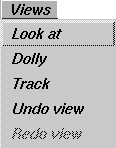
Look at
-
- Changes the view in the graph editor so that all selected curves, keyframes, and tangents in the action lister are visible.
-
- The time and location ranges displayed in the graph editor are bounded by the lowest and highest time and location values of all selected items.
-
- To use this tool:
-
1
-
Select the items you want to look at.
-
2
-
Select Views > Look at. The view changes to show the full extent of the selected items. The other curves, keyframes, and tangents are still displayed, but they may not be visible, or may be only partly visible if they do not lie fully within the bounds of the new view.
Dolly
-
- Zooms in or out of a particular view.
-
- Click in the graph editor or timeview at the point you want as the center of your new view. Drag the dolly box out, then release the mouse.
- If you use the left or middle mouse button to make the dolly box, you dolly in to the view encompassed inside the box.
- If you use the right mouse button to make the dolly box, you dolly out so that the current view fits inside the area of the dolly box.
- If you hold down the Alt and Shift keys while pressing the right mouse button, you can perform direct dollying (moving the mouse to the right zooms in and moving it to the left zooms out). Direct dollying is always available: you do not need to select the Dolly function from the
Views menu to use it.
Track
-
- Tracks the view horizontally and vertically.
-
- Click in the graph editor or timeview, and drag your mouse around to change the view:
- the left mouse button tracks horizontally and vertically.
- the middle mouse button tracks horizontally only.
- the right mouse button tracks vertically only.
-
If you hold down the Alt and Shift keys while pressing the
middle mouse button, you can perform direct tracking,
where the view follows the motion of the mouse. This is
the same as performing a normal, unconstrained track,
except that direct tracking is always available: you do not
need to select the Track function from the Views menu to
use it.
Undo View
-
- Undoes previous operations on the view, such as track, dolly, or lookat. Undo View
keeps a history of transformations, so that if you repeat Undo View, it will undo further back in the history.
Redo View
-
- Re-creates what was undone by Undo. Use Redo View to reverse the last operation from Undo View. You can redo as many operations as you undid with Undo View.
|
|
|
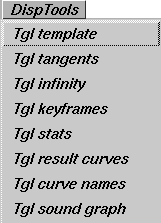
DispTools Menu
Use the DispTools menu to change the display of various items in the graph editor. All of its choices are toggles.
Tgl template
-
- Puts a curve in a templated mode. The curve appears in gray, and has no keyframes or tangents on it. (This behavior is similar to the Display > Tgl template function in the main Alias window.)
-
- To template a curve, pick the curve (either in the action lister or using Pick > curve), and select DispTools > Tgl template. If the curve was templated, pick the curve using Pick > Template, and select DispTools > Tgl template to untemplate it. A templated curve cannot be picked in the graph editor, although it may still be picked in the action lister.
Tgl tangents
-
- Turns the display of curve tangents on or off. By default, tangents are not displayed.
Tgl infinity
-
- Turns the display of the curve beyond the action's defined time range on or off. See ActionTools on page 168 for the various out-of-range types.
Tgl keyframes
-
- Turns the display of keyframes on parameter curve actions on or off. Keyframes are displayed with a small box if they are locked, and with a small X when they are not locked.
|
|
|
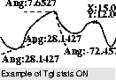
Tgl stats
-
- Turns statistical information about keyframes and tangents on or off.
-
- If Tgl stats is on and a keyframe is picked, the (X, Y) co-ordinates of the keyframe are displayed. If a tangent is picked, the angle of the tangent is displayed.
Tgl result curves
-
- Turns the display of channels on or off.
- If a channel is animated by a single action, the action will still be displayed even when you hide the result curves.
- If a channel is animated by more than one action, toggling result curves off will still show the channel's individual actions, but will hide the display of the resulting channel animation.
Tgl curve names
-
- If a channel is animated by a single action, then toggling Tgl curve names on will display the name of that action beside the channel name in the action lister. If the channel is animated by an expression, then the expression will be displayed beside the channel name, instead.
Tgl sound graph
-
- Shows a graphical representation of the sound data in your animation.
|
|
For more information about
using sound files, see the
Sound Options in Animation
> Playback options on
page 81.
|
-
- The higher the amplitude in the graph, the louder the recorded sound. You can use the sound graph to match movements of your animating objects with specific sound cues. You can display the sound graph by viewing only the left or right sound channels, both at once, or an average of the two channels. To flip between these four different display modes, click in the sound graph.
|
|
|
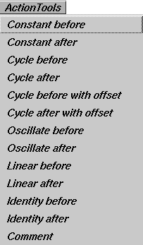
ActionTools Menu
Use the ActionTools
menu to change the behavior of curves outside their defined range. You can also add comments to your actions.
Defining Actions
Actions are defined over a certain time range:
- Parameter curve actions are defined over the range of time between their first and last keyframes.
- Motion path actions are defined over the range of 0 to 100. If the current frame is outside the range of the action, the action must still take on a value.
|
|
You can display how an
action is evaluated out-of
range by selecting DispTools
> Show infinity.
|
The ActionTools menu lets you specify how the curve should be evaluated when it is out-of-range of the first and last defined times. The Before types specify how the curve should be evaluated before the first defined time; the After types specify how the curve should be evaluated after the last defined time.
Constant Before/After
|
|
|
-
- Constant Before means that the curve retains the same value as the value of the first keyframe (or at time 0 for motion path actions) for all time values before this first keyframe.
-
- Constant After
means the value of the last keyframe (or at time 100 for motion path actions) is used for all time values after the last keyframes. This is the default out-of-range type for parameter curve actions.
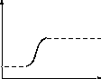
Cycle Before/After
|
|
|
-
- Cycle Before means that the curve repeats itself before the first keyframe. This is like the curve being copied and pasted repeatedly before the first keyframe.
-
- Cycle After
means that the curve repeats itself after the last keyframe. This is like the curve being copied and pasted repeatedly after the last keyframe.
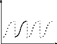
Cycle Before/After with Offset
|
|
|
-
- Cycle Before with offset is the same as Cycle Before, except it continues backwards vertically from where the previous cycle left off. (It does not start from the same vertical position each time.)
-
- Cycle After with offset is the same as Cycle After, except it continues vertically from where the previous cycle left off.
-
-
Oscillate Before/After
|
|
|
-
- Oscillate Before and Oscillate After means that the curve repeats itself backwards, then forwards, then backwards, and so on. This is as if a copy of the curve was taken, and first glued to the curve in the reverse (or mirror) direction, then in the forward direction, then in the mirror direction, and so on.
Linear Before/After
|
|
|
-
- Linear Before means that the curve continues in a straight line along the in-tangent of the first keyframe.
-
- Linear After means that the curve continues in a straight line along the out-tangent of the last keyframe. Since motion path actions do not have editable tangents, linear means that the curve continues along the actual tangent of the curve.
Identity Before/After
|
|

|
-
- Identity Before and Identity After means that the curve continues in a straight line at a slope of 45 degrees (or parallel to the line y = x starting at the first/last keyframe). This is the default out-of-range type for timewarp actions created with Anim > Time tools.
Comment
-
- Lets you add comments to your actions to remind you of information about that action. This is similar to Object Edit > Edit comment, which lets you add comments to objects in the modeling world.
-
- Pick one curve in the graph editor, and select Edit Comment. A shell window running an editor is opened, and you can add new comments or edit previous ones for the action. When you quit the editor, the window closes and you can continue working.
|
|
|
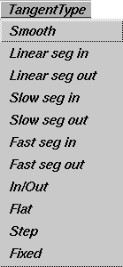
TangentType Menu
The TangentType menu is both a mode and a function, and it operates on currently picked keyframes.
- To use it as a mode, select the desired tangent type from the menu, and then use CurveTools > Append keyframes or CurveTools > Insert keyframes to add new keyframes to an action. As each keyframe is added, the new keyframe's tangent is computed based on the current tangent type.
- To use it as a function, pick keyframes from some curves, and select the desired tangent type from the menu. All picked keyframes have their tangents recomputed to use the selected tangent type.
Tangents control how a curve behaves as it leaves one keyframe and enters the next. The display of tangents can be toggled on or off using DispTools > Tgl tangents.
Tangent Types
Keyframe tangents have tangent types. All of the tangent types except for Fixed cause the tangents to be recomputed whenever the keyframe is moved, so that the characteristics of the tangent type will be maintained. For example, if a keyframe's in-tangent is Linear seg in, then the in-tangent of the keyframe will always point to the previous keyframe. If the keyframe is moved, the in-tangent will be updated to continue to point at the previous keyframe. If a tangent type is Fixed, this means the tangent will not change angles when you move the keyframe. You must explicitly move a Fixed tangent to change its angle.
For finer control of a keyframe's tangent, pick the tangents using Pick > Any tangents, Pick > In tangents or Pick > Out tangents, and then use Xform > Move to adjust the tangent. This will cause the modified tangent's type to become Fixed.
|
|

|
Smooth
-
- A smooth transition is made between the keyframe before and the keyframe after the selected keyframe. Its tangents are co-linear (that is, they are both at the same angle). This ensures that there is no jerkiness at the keyframe.
-
- The angle of the tangents is a weighted average of the slopes between the two keyframes on either side of the new keyframe. Setting a keyframe to Smooth
sets the tangent type of the in- and out-tangent of the keyframe to smooth.
|
|

|
Linear seg in
-
- The action is in a straight line between the previous keyframe and the selected keyframe. The out-tangent of the previous keyframe and the in-tangent of the selected keyframe lie along this straight line.
-
- Setting the tangent type of a keyframe to Linear seg in changes the in-tangent type of the picked keyframe to linear and the out-tangent type of the previous keyframe to linear.
|
|

|
Linear seg out
-
- The action is in a straight line between the selected keyframe and its next keyframe. The out-tangent of the selected keyframe and the in-tangent of its next keyframe lie along this straight line.
-
- Setting the tangent type of a keyframe to Linear seg out changes the out-tangent type of the picked keyframe to linear and the in-tangent type of the next keyframe to linear.
|
|

|
Slow seg in
-
- The movement slows as it enters the keyframe. Setting the tangent type of a keyframe to Slow seg in changes its in-tangent type to slow and the out-tangent type of the previous keyframe to fast.
|
|

|
Slow seg out
-
- The movement is slower at the beginning of the curve segment following the keyframe. Setting the tangent type of a keyframe to Slow seg out changes its out-tangent type to slow and the in-tangent type of the next keyframe to fast.
|
|

|
In/Out
-
- The movement eases out of the new keyframe, and eases in to the next keyframe. Setting the tangent type of a keyframe to In/Out changes the out-tangent type of the picked keyframe and the in-tangent type of the next keyframe to in-out.
|
|

|
Fast seg in
-
- The movement is faster going into the selected keyframe. For example, a car accelerating. Setting the tangent type of a keyframe to Fast seg in changes the in-tangent type of the picked keyframe to fast and the out-tangent type of the previous keyframe to slow.
|
|

|
Fast seg out
-
- The movement is faster going out of the selected keyframe, as in the example of throwing a ball. Setting the tangent type of a keyframe to Fast seg out changes the out-tangent type of the picked keyframe to fast and the in-tangent type of the next keyframe to slow.
|
|

|
Flat
-
- The in- and out-tangents of the new keyframe are horizontal (that is, with a slope of 0). Setting the tangent type of a keyframe to Flat changes the in- and out-tangent types of the picked keyframe to flat.
|
|
 S
t
e
p S
t
e
p
|
Step
-
- The out-tangent of the new keyframe is flat. The curve segment is also flat (horizontal) until the next keyframe, at which point it jumps up or down to the value of that keyframe.
-
- The step tangent type is useful for animating Boolean (ON/OFF) values such as DAG node visibility, or the presence/absence of a light's shadows. A value larger than 0.5 means ON, and less than 0.5 means OFF. Setting the tangent type of a keyframe to Step changes the out-tangent type of the keyframe to step.
>
|
Note:
|
If a keyframe's out-tangent type is step, then it is irrelevant
what the in-tangent type of the next keyframe is as it will be
ignored.
|
Fixed
-
- The tangents of the selected keyframes become fixed at their current angles. A tangent type that is Fixed means the value of the angles will not be changed unless you explicitly modify the tangent. This can be useful if you set a tangent to a certain angle which you would like to maintain even if the keyframe or the segments around the keyframe are modified.
|
|
|
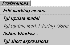
Preferences Menu
Edit marking menus
-
- Let you edit a marking menu shelf.
-
- To display an Action Window marking menu:
-
1
-
Press and hold Shift and Ctrl simultaneously.
-
2
-
Click and hold a mouse button anywhere in a window.
-
3
-
To select a command, drag in the direction of the command. As you drag, a rubber band line is drawn from the center of the menu that follows the cursor.
-
- To edit a marking menu:
-
1
-
Select Preferences > Edit marking menus. A shelf window for the current tools in the marking menu is displayed:
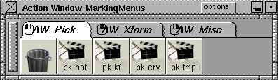
-
2
-
To change the items used in a marking menu, modify the contents of folders by dragging and dropping the appropriate tools.
-
To delete an individual tool, click and drag the tool with
the middle mouse button into the trash can. To delete a
folder, click the folder tab with the middle mouse button
and drag it into the trash can.
-
- Assigning mouse buttons:
-
- Mouse buttons can be assigned to folders. For example, you might want to assign the left mouse button to the pick tools folder and the middle mouse button to the xform tools
folder. The mouse icon in the folder tab corner indicates which mouse button the items are assigned to.
Tgl update model
-
- Lets you specify whether or not transforming keyframes or curves within the Action Window will also update the modeling windows. If Tgl update model
is selected, the Tgl update model during Xform option is displayed in the menu.
Tgl update model during Xform
-
- Select this option for updates to occur during a transformation; de-select it for updates to occur just after the transformation.
|
|
You can always perform a
viewframe by clicking on the
frame indicator in the Action
Window (see Animation >
Action window on page 138).
|
-
- Warning! The updates are done by performing viewframe operations, which may make performance very slow.
Action Window
-
- Closes the Action Window and returns you to the modeling views.
|
|
For example, the label
X_Translate is shortened
to TX, Y_Translate to TY,
and Z_Translate
to
TZ.
|
Tgl short expressions
-
- Lets you toggle between displaying expressions normally and displaying them in short form.
-
- For example, sphere:x_Translate is shortened to sphere:xt, and you can type any of the following:
|
|
Short expressions are not
case sensitive. Any
combination of characters
and the underscore, "_" is
recognized.
|
-
sphere: xt
sphere: tx
sphere: Tx
sphere: t_x
sphere: x_t
sphere:x_Translate
Using Expressions
|
|
|
|
|
Expressions are available in Alias AutoStudio, and are purchasable options for PowerAnimator and Advanced Animation for Studio
This section describes the syntax or rules to be followed when entering an expression, and a discussion on the valid mathematical operations.
Expressions give you the ability to establish dynamic links between animatable parameters so that a change in one parameter (as in the rotation of a joint) can cause another parameter (as in the deformation of a surface) to be updated automatically. The expression system provides simple mathematical operations (+ - * /), most of the functions supported by SDL, and allows references to DAG nodes and CV parameters, as well as the current frame value. Any animatable parameter can have an expression defined to calculate its value.
Expressions are created using the Timeview window in the Action Window. Any parameter that is not currently animated can have an expression attached to it (use Edit > Clear to remove existing animation from an animation parameter). To enter an expression, double-click in the list area next to the desired parameter. Alternatively, you can use the Action Window's Edit > Edit expression function to edit or create an expression using the external editor defined in Alias Preferences.
Referring to other parameters
You can define expressions to establish a dependency relationship between one parameter and another. For example, the X translation of one object could be related to the X translation of another object.
|
|
See the following sections
for more information.
Expression references can
only refer to DAG nodes
(and their CVs). For
example, references to
shader and light parameters
are not supported.
|
Parameter references are defined as follows:
ObjectName[.CVreference]:Parameter
- Object Name is the name of the object (DAG node) that you want to refer to. CV reference is an optional qualifier which lets you specify a CV.
- Parameter is the specific parameter you want to reference.
DAG node references
Within a DAG hierarchy it is possible to reference DAG nodes "higher" up in the hierarchy using a relative reference. A single period (.) is used to specify the current DAG node. Two periods (..) represent the DAG node above the current one. A backslash (\) at the start of the reference represents the highest possible DAG node above the current one. A backslash can also be used to separate multiple upward references.
For example, assume that you have the following hierarchy defined (where levels to the "left" are "higher" than levels to the "right"):
BaseLevel::SubLevel1::SubLevel2::object


For example:


Fluffy::Shoulder::Paw::mySphere
Then relative references to the object mySphere can be created as follows:
.
|
mySphere
|
..
|
Paw
|
..\..
|
Shoulder
|
..\..\..
|
Fluffy
|
\
|
Fluffy
|
Relative references are maintained even if intervening levels are added or removed. So if Paw was removed the following would then refer to Shoulder ..:
The advantage of a relative reference is that when the expression is copied from one object to another, it will reference the new object's DAG hierarchy, whereas an explicit, non-relative reference would continue to reference the old object's DAG hierarchy.
CV references
The parameter of any CV within a surface may be referenced as shown in the following table:
|
Object
|
Reference
(where # represents a number)
|
Example
|
|---|
|
surface
|
u#v#
|
plane.u3v0
|
|
curve
|
u#
|
curve.u1
|
|
curve within a face
|
c#u#
|
curve#3.c2u3
|
|
polysets
|
v#
|
polyset.v27
|
Valid Parameters
For DAG node references, you can use the following parameters:
|
X_Translate or tx
|
Local X Translate of the DAG node
|
|
Y_Translate or ty
|
Local Y Translate of the DAG node
|
|
Z_Translate or tz
|
Local Z Translate of the DAG node
|
|
X_Rotate or rx
|
Local X Rotation of the DAG node, in degrees
|
|
Y_Rotate or ry
|
Local Y Rotation of the DAG node, in degrees
|
|
Z_Rotate or rz
|
Local Z Rotation of the DAG node, in degrees
|
|
X_Scale or sx
|
Local X Scale factor of the DAG node
|
|
Y_Scale or sy
|
Local Y Scale factor of the DAG node
|
|
Z_Scale or sz
|
Local Z Scale factor of the DAG node
|
|
Visibility
|
A Boolean specifying whether or not this DAG is visible
|
For CV references, you can use the following parameters:
|
X_Position or px
|
Local X Position of the CV
|
|
Y_Position or py
|
Local Y Position of the CV
|
|
Z_Position or zp
|
Local Z Position of the CV
|
|
Weight
|
The weighting factor for this CV
|
Short Expression Names
Short expression parameter names such as "tx", "ty", "sx" and "rX" are automatically expanded to their full names. You can also display names in the form "TX".
Examples of valid parameters
|
sphere:X_Translate
|
X Translate of the object sphere
|
|
sphere.u2v3:X_Position
|
X position of the u2v3 CV within the object sphere
|
|
..\..:X_Translate
|
X Translate of the DAG node two levels "up"
|
Mathematical Functions
In addition to the normal mathematical operators (+, -, *, /), all SDL functions which evaluate to a SCALAR may be used in an expression.
The following list provides a brief description of each function, along with the expected parameters.
- The standard trigonometric functions:
|
acos(radians)
|
acosd(degrees)
|
|
asin(radians)
|
asind(degrees)
|
|
atan(radians)
|
atand(degrees)
|
|
atan2(value, value)
|
atan2d(value, value)
|
|
cos(radians)
|
cosd(degrees)
|
|
cosh(value)
|
|
|
sin(radians)
|
sind(degrees)
|
|
sinh(value)
|
|
|
tan(radians)
|
tand(degrees)
|
|
tanh(value)
|
|
- Bessel functions (type man j0 in UNIX for more information about these functions):
|
besselj0(value)
|
besselj1(value)
|
|
besseljn(order,value)
|
besselyn(order, value)
|
- The smallest whole number greater than value:
-
ceil (value)
- Constrain value such that it is an integer multiple of by between start and end:
-
constrain (start, end, by, value)
- Error functions (type man erf in UNIX for more information about these functions):
-
erf (value) erfc (value)
-
fabs (value)
- The greatest whole number less than value:
-
floor (value)
- Floating point remainder of
value / divisor:
-
fmod (value, divisor)
- Gamma function (type man gamma in UNIX for more information about this function):
-
gamma (value)
- Return a random number using a standard Gaussian distribution:
-
gauss ()
- Length of the diagonal of a rectangle with sides of lengths x and y (type man hypot in UNIX for more information about this function):
-
hypot (x, y)
-
log10 (value)
-
pow (value, power)
- Return a random number in the range -1.0 to 1.0 with a pseudo-random distribution:
-
rand ()
- Use the argument seed as a seed for a new sequence of pseudo-random numbers:
-
srand (seed)
- Return 0.0 if value is 0.0, 1.0 if value is positive and -1.0 if value
is negative:
-
sign (value)
-
sqrt (value)
- Evaluating action curves:
-
animate (action curve, expression)
-
The value of the animate function is the value of the curve
action curve at the frame given by the expression. For
example, animate (curve, frame - 2) returns the
value of the animation curve curve at 2 frames less than
the current frame.
|
|
You can see the name of any
action in the Action Window
(see DispTools > Tgl curve
names in the Action
Window).
|
>
|
Note:
|
The animate function takes an action curves, not a channel,
as its first argument. Thus, it does not reference a parameter
such as sphere:X_Translate, but rather the action curve
that might be animated such a parameter (for example,
sphere.X_Translate or my_curve).
|
|
|
As a convenience, you can specify a parameter or channel
reference when entering an animate function into an
expression by enclosing the reference within braces, as in
animate ({sphere:X_Translate}, frame). However,
note that this is immediately translated into a reference to
the action curve currently animating that parameter, so it is
still not a true channel reference.
|
-
- The animate function provides two very useful capabilities:
-
1
-
It is possible to refer to the position of an object at a time other than the current frame.
-
2
-
It can be used as a mechanism for defining your own functions within expressions.
Logical operations
Logical operations include:
- comparisons (==, !=, >, <, >=, <=)
- Boolean operators (&&, || !) )
These can be used wherever a value is allowed. A logical operation which is TRUE evaluates to 1.0, and a logical operation which is FALSE evaluates to 0.0.
An example of a logical operation would be to set the position of an object based upon a decision. The algorithm would be as follows:
-
if the distance along the X axis between a cube and a cone
is less than 3 units
-
then return the pyramid's X Translate value less 4 units
-
otherwise return the cube's X Translate value less 5 units
This algorithm would be entered as:
((fabs (cube:X_Translate - cone:X_Translate) < 3) *
(pyramid.X_Translate - 4)) +


((fabs (cube:X_Translate - cone:X_Translate) >= 3)
* (cube:X_Translate - 5))
Expression Examples
The following are a few different examples of how expressions can be used. For purposes of the examples, expressions will be written out in the form:
parameter = some expression
For example, sphere:X_Translate = sin (frame), means that the expression sin (frame) is to be applied to the X_Translate channel of the object sphere.
|
|
Turn Expression updates
during XForm ON to see the
expressions update while
you move the mouse (See
Preferences > Performance
options in Basic Tools).
|
Also, all of the examples are built in a Y-Up orientation.
A simple finger
You can get some realistic finger motion by creating a simple expression relationship between each finger joint. A finger with five joints (named joint, joint#2, joint#3, joint#4 and joint#5, with joint#5 being the finger tip), will behave nicely if the rotation of each joint is set to the rotation of the finger tip. Apply the following expressions to the finger::
joint:Z_Rotate
|
=
|
joint#5:Z_Rotate / 2
|
joint#2:Z_Rotate
|
=
|
joint#5:Z_Rotate
|
joint#3:Z_Rotate
|
=
|
joint#5:Z_Rotate
|
joint#4:Z_Rotate
|
=
|
joint#5:Z_Rotate
|
|
|
Expressions may be copied
and pasted within the Action
Window just like any other
animation channel (See Edit
> Copy and Edit > Paste in
the Action Window).
|
This establishes the rotational relationship between the finger joints. Now as the finger tip (joint#5) is rotated about the Z-axis (using Xform > Rotate), the other joints will rotate an equal amount, giving a very realistic motion to the finger.
Interlocking gears
Expressions may also be used to create mechanical devices; for example, gears. A mechanical relationship with four gear objects (gear, smallGear, link#1
and link#2) , with gear
as the control object, could be established with the following expressions:
smallGear:Y_Rotate
|
=
|
gear:Y_Rotate * -2
|
link#1:Y_Rotate
|
=
|
- gear:Y_Rotate
|
link#2:Y_Rotate
|
=
|
- link#1:Y_Rotate
|
Notice that the smallGear is half the size of gear, and should then rotate twice as fast as gear. The negative sign in front of each reference causes the gears to rotate in opposite directions.
Creating control objects
Establishing relationships between various objects is a very powerful use of expressions. It is also possible to create objects that are simply there to help control (or influence) the motion of other objects.
The following expressions give an example of a scale and object relationship:
rightTape:X_Scale
|
=
|
(control:X_Translate / 2) + 4
|
rightTape:Z_Scale
|
=
|
.:X_Scale
|
leftTape:X_Scale
|
=
|
18.5 - rightTape:X_Scale
|
leftTape:Z_Scale
|
=
|
.:X_Scale
|
The next expressions establish a link between the size of the object and the amount of rotation for the object:
rightReel:Z_Rotate
|
=
|
log10 (1 + ((rightTape:X_Scale - 4) / 1.5)) * 36000
|
leftReel:Z_Rotate
|
=
|
log10 (1 + leftTape:X_Scale - 4) / 1.5)) * 3600
|
For the purposes of animating an object, set keyframes on the position of the control object itself. (To see a sample animation, just select Animation > Playback).
Relating shader parameters
While expressions may only refer to DAG node parameters, they may be applied to any parameter which may be animated. This particular example shows how a small puff of dust (using particles) may be produced when an object bounces on the ground. In general what we will do is adjust the rate of particle emission for a small stand-in object so that particles are emitted when the object touches the ground. The stand-in object will be positioned at the point of contact between the object and the ground.
The expression which is applied to the dust shader (albeit very simplistic) is:
dust:psys_particles_per_sec
|
=
|
(ballObject:Y_Translate < 0.25) * 500
|
Now if you select Anim > Run dynamics, as the ballObject bounces, little puffs of dust will be emitted (this is a simplistic example: as the ball settles, more "dust" will be emitted)
Notice how this expression uses the logical operation to compare the position of the ballObject, and then set the particle emission accordingly. Expressions may be applied to any shader parameter, particle emission was chosen because it produces an immediately visible result.
Following animated objects
The animate function provides an expression writer with the ability to evaluate an animation curve at any particular frame. This capability could be used to have objects follow each other by having them share the evaluation of the same animation curve.
For this particular example there are three spheres which follow each other around. The lead sphere (sphere) is animated using keyframe animation, and has two animation curves (yTrans for the Y_Translate channel, yRotate for the Y_Rotate channel). The other two spheres follow 5 and 10 frames behind the lead sphere.
The expressions that define this animation are:
sphere#2:Y_Translate
|
=
|
animate (yTrans, frame - 5)
|
sphere#2:Y_Rotate
|
=
|
animate (yRotate, frame - 5)
|
sphere#3:Y_Translate
|
=
|
animate (yTrans, frame - 10)
|
sphere#3:Y_Rotate
|
=
|
animate (yRotate, frame - 10)
|
sphere#3:X_Translate
|
=
|
sind (frame * 3.6) - 6
|
The last expression is added just to make the third sphere behave a little differently.
Any scalar value can be used for the second parameter to animate, including another animate function. The second parameter is simply an expression whose value will be used as the frame to evaluate the action curve. Evaluation of the action curve outside its defined range follows the settings for the extrapolation type for the curve (see ActionTools in the
Action Window).
Modulating an animation over time
The animate function also allows you to modulate the evaluation of an animation curve over time. This example shows a swinging pendulum which slows down over time. The basic pendulum swinging was done as a keyframe animation from frames 0 to 60. The expression on the pendulum then uses the animate function to evaluate the curve at the current frame, and then modulates the results based upon the overall length of the sequence.
The expressions that form the animation include:
pendulum:Z_Rotate
|
=
|
animate (animNode.Z_Rotate, fmod (frame, 60)) *
((animNode:X_Rotate - frame) / animNode:X_Rotate)
|
animNode:X_Rotate
|
=
|
500
|
The second parameter to the animate function is set to range between 0 and 60 (the original range of the keyframes). A similar result could have been achieved by just using animate (animNode.Z_Rotate, frame) and then changing the extrapolation on the animNode.Z_Rotate curve to cycle after.
Notice how animNode:X_Rotate is being used as a simple variable. That way if the timing of the sequence needs to be changed, only the value of animNode:X_Rotate needs to be changed. All other expressions will then be evaluated using the new value.
Defining your own functions
For this example, the apply Function plugin was used to create an animation curve that represents the evaluation of a noise function over the range 0 to 100. The animate function is then used to index into the resultant animation curve (in effect "evaluating" the function). The sphere has a normal keyframe animation for its rotation, and the following expression:
sphere:Y_Translate
|
=
|
animate (Noise, frame)
|
The noise "function" could also be used to modulate the evaluation of other animation curves, in effect supplying a follow-type expression with a slightly random but controllable behavior.
In the same example, sphere#2 was animated using keyframe animation, and then sphere#3 has a "follow" type series of expressions, with the Noise "function" being used to add a little randomness to the follow of the X_Translate:
sphere#3:Y_Rotate
|
=
|
animate (sphere#2.Y_Rotate, frame - 5)
|
sphere#3:X_Translate
|
=
|
animate(sphere#2.X_Translate, frame - 5) -
(animate (Noise, 60 + fmod (frame, 15)) * 0.375)
|
For the X_Translate, the Noise "function" is evaluated over the range from 60 to 75.
|


