High-Tech And Vertex Juggling -
NVIDIA's New GeForce3 GPU
|
It's now for almost 2 years that NVIDIA is ruling the 3D graphics chips scene in terms of 3D-performance. From a technological point of view, NVIDIA's chips weren't shabby either. Particularly the integration of a transform and lighting engine into a mainstream 3D chip, as done for the first time with NVIDIA's GeForce256 in late 1999, and the methodical development of this technology can be seen as NVIDIA's biggest claim to fame. However, while NVIDIA's GeForce2 Ultra chip may be the unchallenged leader in 3D-performance today, it is ATi's Radeon product, released in July 2000, which comes with the most sophisticated features right now. The technology of ATi's Radeon includes things like keyframe interpolation, four-matrix skinning, environment bump mapping, (proprietary) 3D-textures and HyperZ, while GeForce2 owners have to do without them. In July 2000, when Radeon was released, ATi was proud to announce that their latest chip supports several features of Microsoft's upcoming DirectX8 specification. NVIDIA admitted that GeForce2 is only supporting DirectX 7 features, but made a strong case saying that Radeon was far from a full-DirectX8 implementation. Finally now NVIDIA's mysterious successor of the GeForce2, well known under its code name 'NV20', is ready to be released and NVIDIA is once more proud to announce that this new 'GeForce3' chip is fully supporting Microsoft's latest DirectX version, which happens to be DirectX 8.
(Almost) No Benchmarks ... Yet
This article is supposed to introduce the vast amount of GeForce3's new features. It is trying to show you the benefits of its DirectX8 implementation, but also checking for some possible flaws. You won't find any benchmark results in this first piece that I am writing about GeForce3, because those are not supposed to be published before GeForce3 has got a bullet proof set of drivers. However, right now those 'bar graphs' may not be the biggest catch. The really impressive part of GeForce3 is its new technology. The name 'GeForce3' may make it look as if it was a mere successor of NVIDIA's two previous chips GeForce256 and GeForce2, but while it may still include quite a bit of the technology of its predecessors, its new technology is certainly marking a quantum leap for what will be possible in future 3D-applications.
There are actually a few benchmark results hidden in the article. Good luck finding them!
GeForce3 and DirectX8 - Do We Really Need A New Set Of 3D Features ... Again?
Yet another NVIDIA chip and yet another set of features. Does that really have to be true? There are enough people out there using graphics chips that don't even come with integrated T&L. Happy people I might add. Now NVIDIA teaches us that integrated TnL is already old news. What it takes are programmable vertex and pixel processors. Thank God you will find out that GeForce3 has got some features that you can benefit from right out of the box, because those other new DirectX8 gimmicks won't be implemented into 3D-games for quite a while. This is certainly a shame, because GeForce3 is an impressive product, but should you really pay for it right now?
What we have to keep in mind is that GeForce3 is the first 3D-platform that comes with a very similar feature list as Microsoft's upcoming Xbox. Bringing those features to market now might prove very beneficial for the Xbox.
You will have to decide for yourself if you consider GeForce3 worth the $599 is will probably cost once it's out. It is certainly the most feature rich product I have ever reviewed. Get ready for the longest article in the 5-year history of Tom's Hardware Guide. It will be a high-tech roller coast ride.
The General Features Of
GeForce3
NVIDIA's latest chip comes up with several impressive numbers:
- Process: .15u
- Transistors: 57M
- Pixel Pipelines: 4
- Simultaneous Textures Per Pixel: 2
- Maximum Active Textures Per Pixel per Pass: 4
- Number of Pixel Shading Operations per Pass: 36 (4 per combiner, 9 combiners)
- Vertex Instructions Per Vertex per Pass: 128
- Core Frequency Of Released Card: 200 MHz
- Memory Frequency Of Released Card: 230 MHz DDR
- Frame Buffer Of Released Card: 64MB
- Supported Memory: SDR or DDR
- Memory Interface Width: 128-bits
GeForce3 has no less than 57 million transistors, which is more than double the amount of transistors found on GeForce2 chips. Even Intel's latest processor, the Pentium 4, comes with over 20% less transistors. To avoid that this huge amount of gates requires a very large silicon die, GeForce3 is manufactured in 0.15-micron process. This further shrink down from the previous 0.18-micron process of the GeForce2 line of chips is also required to enable high clock rates and low power consumption of NVIDIA's new monster chip.
On the first look some other numbers make it seem as if GeForce3 shares quite a few hardware features with its predecessor GeForce2. There are still four pixel pipelines and two simultaneous textures that can be applied to a pixel. The memory interface is still 128-bit wide and clocked at 230 MHz (460 MHz DDR), which seems to make it identical to GeForce2 Ultra. The core clock of GeForce3 is with 200 MHz even lower than the 250 MHz found on GeForce2 Ultra cards.
As you read on you will learn however, that the 57 million transistors of GeForce3 were certainly not wasted. Even though GeForce3 might have several general spec numbers that sound as if NVIDIA's new chip is only little advanced over the GeForce2 line of 3D-chips, you will find that almost each feature of GeForce2 was significantly advanced, making GeForce3 a chip with several excellent technologies that even put GeForce2 Ultra cards to shame. Let's go through those advances one by one.
According to my old tradition, I will discuss those new
technologies in the succession as they influence the 3D-pipeline. The below
graph should give you a basic overview:
GeForce3's New Vertex Shader - A Poor Name For A Great Set Of Features
The new so-called 'Vertex Shaders', first part of GeForce3's 'nfiniteFX Engine' is one major, if not the most important new feature of GeForce3, using a major amount of the 32 million transistors that GeForce3 has over GeForce2. This unit with the rather badly chosen name is capable of a whole lot more than just 'shading vertices'. I would rather have called it 'Vertex Processor'. It enables developers of 3D applications to apply special programs to each vertex of an object or a complete scene (frame) that are executed within GeForce3, thus not requiring any CPU-resources.
To explain what that actually means I need to go back to the 3D-pipeline.
What you see up there is the first stages of the 3D-pipeline before the view port mapping and the triangle setup. The whole 3D-pipeline is executed for each rendered frame.
First of all the 3D-application, let's say a 3D-game, is providing the game AI, the game physics, responses to user inputs, scene management and more. The tessellation of curved surfaces means the conversion of curved areas (such as e.g. arches) into polygons or rather triangles. It is only done by a few current games. So far this was always done in software and thus executed by the CPU. GeForce3 is able to take over this job and I will get to that later.
The next stage in the 3D-pipeline is the transformation. I have explained it in previous articles, which is why I will keep this a bit short. A frame of a 3D-scene, as displayed on your monitor, consists of several different objects in certain places that are lit by one or several different kind of light sources, seen from a certain viewpoint. I guess this explanation is as basic, but also as complete as it gets. Every object, may it be a player, a wall, the floor or whatnot is made of a certain number of triangles.
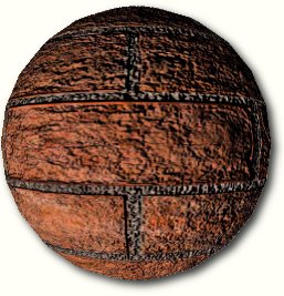
'Vertices' (sing. 'Vertex') are the corners of those triangles that each 3D-object is made of. In fact, the vertices are the very 'virtual matter' that makes a 3D-object. As the game engine transfers the object of a scene to the graphics processor, it actually sends over all the vertices of this object. Each vertex carries a lot of information. First of all there are the 3-dimensional coordinates x, y, z and w (weight). Then there is the color, often specified in form of a diffuse as well as a specular color. This color data is coded in the common 'RGBA' format, for 'red, blue, green and alpha'. The vertex also needs to carry its normal, the vector that points orthogonal off its surface. Then there are the texture coordinates s, t, r and q, which represent the texture and its position for the vertex. A vertex can of course have several texture coordinates in case that more than one texture is supposed to be applied to it. Additionally there might be fog as well as point size information and even more. You can see that a vertex, the smallest unit in a 3D-scene, is carrying a huge amount of descriptions.
You saw the example of the kettle above. It was supposed to represent the definition of a 3D-object as it is sent to the transform engine, using the 'general' or 'basic' 3D-coordinates supplied by the game (model space/world space). Now you can imagine that from your view port (the screen), you might see the kettle from a different angle, a different direction or in a different location (view space). Thus the coordinates of the vertices need to be altered, with the result that each triangle that makes up the kettle might have to be rotated, enlarged/reduced or shifted up, down, left or right. This is what transforming does. It changes the coordinates of the vertices that make up a 3D-object as supplied by the 3D-game to the coordinates that accord to your point of view.
We just learned that the color of each vertex of the kettle as well as the texture(s) that are supposed to be applied to it later and their positions are also carried as information within the vertex data. However, what still needs to be applied to each vertex in order to make this 3D-object visible is the lighting. These much more complex calculations are done by the lighting engine. A lot has to be taken into consideration for those calculations. The number, the type (global, uniform, directional, spot) of each light as well as the way it is being applied (ambient, diffuse or specular) need to be taken into consideration by the lighting engine before the vertex receives its lighting data.
The actual lighting process comes only into play if the game is actually using 'vertex lighting' instead of the today most commonly used 'light mapping', which applies light to a triangle in form of a light texture.
What I just described was the normal work of the already known T&L-unit as found in GeForce256, GeForce2 and ATi's Radeon. GeForce3 does also contain the so-called 'hardwired T&L' to make it compatible to DirectX7 and also to save execution time in case a game does not require the services of the 'Vertex Shader'.
We know now that each vertex carries a considerably huge amount of information, like its coordinates, weight, normal, color, texture coordinates, fog and point size data. The 'vertex shader' allows the alteration of this information with little programs. These programs are executed by the vertex shader itself and do therefore not require any computing power of the CPU. While the classic T&L-engine restricted the influence of the game developer to what happens before the 3D-pipeline reaches the transform level, he can now do whatever he likes with the 3D-objects of his game, and that without any CPU-performance penalty.
The opportunities are huge. The program could alter the coordinates of a vertex, thus basically changing the shape of the object for e.g. realistic movements, motion blur, blending, interpolations (morphing) or deformations. It could change the color values or the texture coordinates and thus the surface appearance of the object for stuff like color effects, reflections, bump map setup (e.g. for Blinn bump mapping) or other projected textures. The lighting can also be influenced almost to the developer's heart's content. There are restrictions however. The possibilities of the vertex shader are not as 'infinite' as NVIDIA managers wanted to make us believe when they baptized it 'nfiniteFX Engine'. The programs executed within the vertex shader can only have a certain size (128 instructions) and the execution time is of course another limiting factor. Let's have a quick look at the details.
The above diagram shows that the vertex shader is able to compute vertices with up to 16 data entries. Each entry consists of 4 32-bit floating-point numbers. 16 entries are quite a lot. It easily fits an average vertex with its position coordinates, weight, normal, diffuse and specular color, fog coordinate and point size information, leaving plenty of space for the coordinates of several textures.
Inside the vertex shader, the data is computed in form of entries. We just learned that each entry is a set of four 32-bit numbers. This makes the vertex shader a SIMD (single instruction multiple data) processor, as you are applying one instruction and affect a set of four variables. This makes perfect sense, because most transform and lighting operations are using 4x4 or 3x3 matrix operations. Each data is treated as floating point value, which shows that all computations executed by the vertex shader are actual floating-point calculations. Basically, the vertex shader is a very powerful SIMD FPU, barely touched by Pentium 4's SSE2 unit.
The next important feature of the vertex shader is its 12 SIMD-registers that can also contain four 32-bit floating-point values. Those 12 registers are what the vertex processor can juggle with. Besides the 12 registers, which can be used for load as well as store, the vertex shader offers a set of 96 4 x 32-bit SIMD constants that are loaded with parameters defined by the programmer before the program starts. Those constants can be applied within the program and they can even be addressed indirectly, but only one constant can be used per instruction, which is a bit of a bummer. If an instruction should require more than one constant, one has to be loaded in one of the registers with a previous load-instruction. The typical use of this large set of constant data would be things like matrix data for the transform (usually a 4x4 matrix), light characteristics, procedural data for special animation effects, vertex interpolation data (for morphing/key frame interpolation), time (for key frame interpolation or particle systems) and more. There is a special kind of vertex programs called 'vertex state program', which is actually able to write to the parameter block. Normal vertex programs are only able to read from it.
The instructions itself are very simple, but therefore also easily understandable. The vertex shader does not allow any loops, jumps or conditional branches, which means that it executes the program linearly one instruction after the other. The maximal length of a vertex program is 128 instructions. After that the vertex should be changed to what the developer intended and it's got to be transformed and lit. If more instructions should be required the vertex can enter the vertex shader once more.
The final result that comes out of the vertex shader is yet another vertex, transformed to the 'homogenous clip space' and lit. It is important to note that the vertex shader is not able to create vertices or to destroy them. One vertex goes in and one vertex comes out.
This information is only for the ones of you who are interested and have a bit of programming experience as well as a minimal understanding of 3D math.
These are the instructions:
| Instruction | Parameters | Action |
| nop | do nothing | |
| mov | dest, src | move |
| mul | dest, src1, rc2 | Set dest to the product of src1 and src2 |
| add | dest, src1, rc2 | Add src1 to src2. [And the optional negation creates subtraction] |
| mad | dest, src1, rc2, rc3 | Multiply src1 by src2 and add src3 - into dst |
| rsq | dest, src | Reciprocal square root of src (much more useful than straight 'square root'). dest.x = dest.y = dest.z = dest.w = 1/sqrt(src) |
| dp3 | dest, src1, src2 | 3 Component dot product |
| dp4 | dest, src1, src2 | 4 Component dot product |
| dst | dest, src1, src2 | Calculate distance vector. src1 vector is (NA,d*d,d*d,NA) and src2 is (NA,1/d,NA,1/d). dest is set to (1,d,d*d,1/d) |
| lit | dest, src | Calculates lighting coefficients from two dot products and a power. src is:
|
| min | dest, src1, src2 | Component-wise min operation |
| max | dest, src1, src2 | Component-wise max operation |
| slt | dest, src1, src2 | dest = (src1 < src2) ? 1 : 0 |
| sge | dest, src1, src2 | dst = (src1 >= src2) ? 1 : 0 |
| expp | dest, src.w |
|
| log | dest, src.w | dest.x = exponent((int)src.w) dest.y = mantissa(src.w) dest.z = log2(src.w) dest.w = 1.0 |
| rcp | dest, src.w | dest.x = dest.y = dest.z = dest.w = 1 / src |
These few instructions are already quite powerful. To make the handling easier, NVIDIA added a few more features, 'costless' negation and swizzling...
There is also a possibility to mask the registers or constants, to access less than all the four values of a data entry.
You can see that despite the small number of different instructions and despite the missing jumps and conditional branches the vertex programs can be pretty powerful. The most important restriction however is clearly the program limitation to only 128 instructions per program and the execution time of at least 1 clock per instruction.
Here are a few examples that list the number of instructions required by a certain operation:
| Vector Cross Product | 2 |
| Division | 2 |
| Square Root | 2 |
| Multiply Vector with Transpose Matrix | 4 |
| Transform To Clip Space, Lit It With One Single Directional Light In World Space, Then Output A Texture Coordinate | 7 |
| High Precision Log | 9 |
| High Precision Exp | 9 |
| Low Precision Sinus / Cosinus | 9 |
| High Precision Sinus / Cosinus | 13 |
| Transform To Clip Space, Lit It With One Single Specular Light In World Space, Then Output A Texture Coordinate | 18 |
| 4 x 4 Matrix Inversion | 38 |
| 17 simple point light sources | 126 |
The Xbox is supposed to have two parallel vertex shaders, while GeForce3 has only one. The 'hardwired T&L' unit cannot be used parallel to the vertex shader. GeForce3 can only process one vertex after another.
NVIDIA supplies small libraries for common 'vertex program modules' as well as 'vertex programs for fixed functions'. It also offers a program (NVLink) that is able to create vertex programs for you. Here is an example program for two-sided lighting:
What always has to be kept in mind is:
- A vertex program must not contain more than 128 instructions. This restricts the number of possible (specular) lights as well as the number of possible matrices for skeletal animations.
- The longer the program the longer the execution time and the lower the triangle rate.
- Use conventional 'hardwired' T&L if vertex programming is not required.
- Switching between a small number of programs is fast, switching between a large number of programs is slow(er). This sounds as if GeForce3 is caching the vertex programs.
- One vertex goes in, one vertex comes out - the Vertex Shader cannot create new vertices, write to other vertices or receive information about other vertices in the same frame.
- The end product has to be a transformed and lit vertex, the program has to make sure of that.
All in all the Vertex Shader specs are very impressive and offer a huge number of possibilities. However, a peep at the specifications of the Xbox shows that in GeForce3 the vertex shader is still in its early days.
A World Of New Opportunities - What The Vertex Shader Can Do
I've got to admit that the heading of this paragraph may be a bit too juicy. It is virtually impossible to list all the things developers are able to do with the new programmable vertex processor of GeForce3. However, I can at least give you a list of the fanciest features that can be realized with NVIDIA's new flagship processor.
Skeletal Animation - Matrix Palette Skinning
We already learned that the Vertex Shader allows a considerably large number of matrices for character animations. This means that the days of NVIDIA's pretty useless 2-matrix-skinnig are finally over. Faces, limbs or clothes can now be animated very realistically. NVIDIA claims that up to 32 matrices (=bones) can be used per vertex for animations. A look at the 128-instructions limitation shows however, that less than 32 'bones' seem to be more realistic. Nevertheless, even 20-matrix-skinning is already a very impressive achievement.
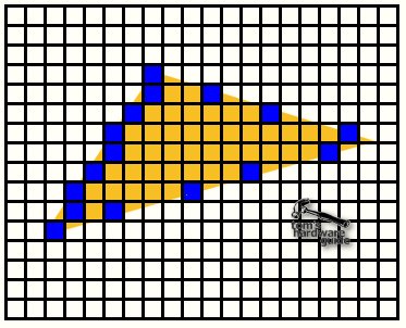
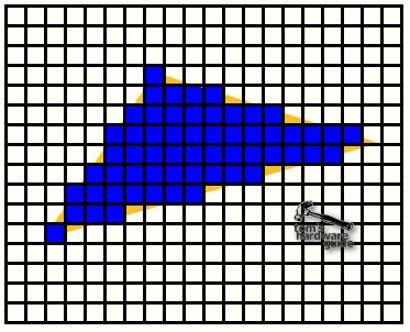
Morphing And Key Frame Animation
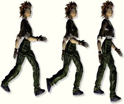
An easier way of creating semi-realistic animation is to define two different stages of an object and then let the vertex shader create interpolation steps in between those two stages. This way you can change a face from smiling to angry, as already shown by ATi with the Radeon, a chip that is already capable of morphing and key frame interpolation. NVIDIA's example is a swimming dolphin.

Another one is this here:

Procedural deformation means that an e.g flat or 'normally' shaped object changes its shape with a special procedure. This can be dynamic (in most cases) as well as static. A typical example would be waves on a water surface, a flag waving in the wind or (static) a metal object hit by gunshots.

Different to 3dfx's approach of producing a motion blur effect rather costly with the T-buffer (costing expensive fill rate), the same effect can also be produced by the vertex shader. Vertices with their normal (the vector orthogonal to its surface position) pointing into the direction of the motion are not changed, the coordinates of vertices with their normal pointing 'backwards' are replaced by the transformed coordinates the same vertex had in the previous frame, which has the effect that the object is stretched 'backwards'. Depending on the motion vector's length (=speed of the object) the alpha value of the vertex is reduced, making it partly see-thru and blurry. You have to admit that it looks very 'realistic'.
Setup For Dot Product Bump Mapping (Per Pixel Bump Mapping)
Since the DirectX7-spec and the rendering hardware of GeForce256, GeForce2 and ATi's Radeon it is possible to use the so-called 'per pixel lighting', which also includes dot product bump mapping. The idea behind 'bump mapping' is to avoid that a surface relief requires any geometric detail. It is much 'cheaper' to apply special 'normal maps' to a triangle, which gives its flat surface a 3-dimensional appearance. Theoretically a 'normal' is a vector that points into the direction that a surface is facing (orthogonal to its surface) and it is required to compute the direction in which a surface reflects light. Dot product bump mapping uses a map that applies 'false' normals to each pixel of a triangle, so that the reflection is not computed in accordance to the 'real' flat triangle surface, but according to the surface vectors of the normal map. This results in the bump mapping effect, giving the surface a 3D-appearance that is not 'really' geometrically there. There is no doubt that dot3 bump mapping is the best bump mapping technique so far.
Here comes a description of normal maps:
Normal maps are simply RGBA textures where the R G and B colors in the range [0,1] are interpreted as < X, Y, Z > unit vectors in the range [-1, 1 ]. Each texel in the Normal Map texture is interpreted as the local unit surface normal. Normal Maps give us a per-pixel description of the surface normal vector of a surface. We typically must convert a unit light vector into a color so that we can perform a per-pixel dot product in the register combiners or texture stages
Unfortunately there is also a downside. Each time a triangle of the bump mapped object is moved or rotated the normals of the normal map need to be transformed again, because their direction changed in relation to the light source or the view port. This transforming of the normal map used to be done in software and thus by the CPU, which made the few games that supported dot3 bump mapping (as e.g. Evolva) rather slow once dot3 bump mapping was enabled.
The Vertex Shader is able to compute the vectors required for the transform of the normal maps, using the so-called 'texture space'. This procedure is also called 'per-vertex dot3-setup'. Further down in the 3D-pipeline the Pixel Shader of GeForce3 transforms the normal map by the vectors supplied by the Vertex Shader to create the normals that are required to display the bump mapping effect. With GeForce3 this whole procedure does not require the CPU, which makes dot3 bump mapping an effect that can be used without a major impact on game performance.
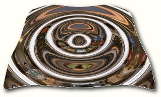
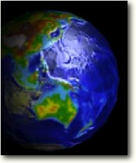
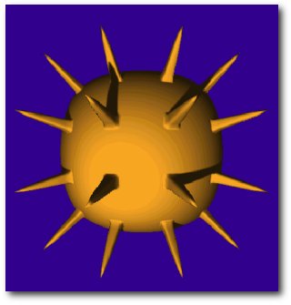
There are a lot of places where refraction comes into account in normal life. First of all we are of course thinking of some special lens effects, as e.g. the fish eye lens example from below. However, looking through a thick glass window or simply through a glass of water shows the same kind of effect as well. Hot air is also able to refract light as we typically know from motor races. The vertex shader is able to simulate any kind of refraction effect once the right vertex program is used.
This is another very impressive example of what the vertex shader is able to do, created with a vertex program that is 27 instructions long. We know the cube environment mapping technique that is required for realistic reflections since DirectX6 and GeForce256. The vertex shader is able to combine this effect with a refraction effect, as you can see in the example.
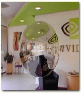
You can see that the glass sphere is reflective as well as having a refraction effect on the area behind hind.
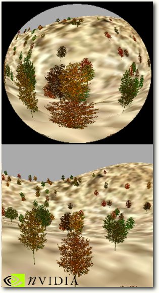
We have learned that each vertex is able to carry 'fog data' and thus it is not hard to imagine that the vertex shader can influence this data, meaning it can add fog of different intensity to different vertices. The layered fog in our example uses the distance that a vertex has to the floor to determine the intensity of the fog. The vertex program checks the distance to the ground and applies the according fog value to the vertex. Sounds pretty simple, doesn't it?
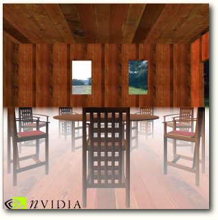
The only question is why there is fog in this room. The windows seem to be open. Maybe the NVIDIA engineer that created this demo was inspired by a colleague that suffers from heavy flatulence.
I don't want you to fall asleep and I think I have introduced just about enough effects enabled by GeForce3's new Vertex Shader. Let me just mention the others that NVIDIA considers important so far:
- Creation of realistic looking fur in combination with the new Pixel Shader.
- Vertex Shader controlled particle systems are able to run completely independent from the CPU.
- Underwater light refraction patterns from the water surface are realized by the Vertex Shader with mesh blending.
- Two-sided lighting allows different lighting characteristics of the front and backside of a triangle.
- Silhouette rendering, membrane lighting, rainbow rendering, anisotropic lighting, toon shading are all custom lighting effects that look rather fancy.
- Perlin noise is probably the most popular procedural noise function, and is very useful for things like clouds, smoke, swirling fog, fire, etc. By being able to run Perlin Noise through the Vertex Shader, GeForce3 can essentially generate procedural effects like smoke, fire and clouds independently from the CPU.
- Many point lights - the vertex shader allows a lot more lights per vertex than the 8 lights previously allowed by DirectX7. NVIDIA has an example with 17 diffuse lights. However, the 128-instruction limit is still restricting the number of possible specular lights.
There is no doubt that the new opportunities enabled by GeForce3's new Vertex Shader are simply amazing. The implementation of this new 'vertex processor' is marking a quantum leap in terms of possible photo-realism in 3D-applications. Microsoft's upcoming Xbox will also be equipped with this feature and even with a beefier version than GeForce3. The currently known Xbox specifications lead to the conclusion that NVIDIA's Xbox chip will come with two parallel vertex shaders.
Unfortunately there are a few problems as well. First of all will we have to realize that it will take a pretty long time until games will finally take proper advantage of the Vertex Shaders. It does not only take some time until developers will have adopted the huge new feature set of the Vertex Shader, but it will also last quite a while until enough systems will be equipped with graphics cards that support vertex programs. As long as only a (rich) minority of people can and will afford GeForce3 cards, game developers would significantly restrict their audience if they would base their games on vertex shader operations. We should remember how long we had to wait for games that made proper use of integrated T&L. GeForce256 was released late 1999 and even today there are only few games that require integrated T&L for a proper operation.
The second question is about the performance of those nifty vertex programs. Right now we don't know if those great effects will be executed fast enough to make them worthwhile. Lovely looking Blinn bump mapped surfaces won't be much appreciated if they should impact game performance.
The Vertex Shader is a great feature and should be well commended. However, it won't be reason enough to go and buy a GeForce3 card right now.
The Programmable Pixel Shader Of GeForce3
The next part of GeForce3's 'nfiniteFX Engine' is the 'Pixel Shader'. Just as its brother the 'Vertex Shader', it is programmable as well. It is a development of GeForce2's NSR = NVIDIA Shader Rasterizer. The surprising thing however is that NVIDIA doesn't supply by far as much information about it as about the Vertex Shader. It almost seems a bit as if NVIDIA is not quite as proud of the Pixel Shader. John Carmack's recent comments about GeForce3's pixel rendering unit seems to point in the same direction. They weren't all that flattery.
What Happens In The 3D-Pipeline Before The Pixel Shader?
First of all I guess I need to explain what the Pixel Shader stands for. It's basically the part of GeForce2 that does the rendering of the actual pixels that make up the image on your screen. Let's have a look what happened in the 3D-pipeline so far.
![]()
The vertices of the 3D-scene left the vertex shader as transformed and lit vertices. The next stage was the clipping, which removes all vertices of the scene that are not within the area of the screen. Back Face Culling removes all vertices that are facing 'back', away from the viewer, and thus don't show up on the screen. The viewport mapping is finally transforming the x and y coordinates of the vertices to viewport coordinates.
Now there comes the triangle setup. This is where the life of the vertices ends and the life of the pixels begins. It also marks the change of the 3D-scene from 'real' 3D to 'virtual' 3D or 2D. The computer screen is only 2D after all, so the final frame has got to be 2D as well.
The triangle setup computes triangle for triangle the parameters required for the rasterization of the triangles, amongst other things it defines the pixel coordinates of the triangle outline. This means that it defines the first and the last pixel of the triangle scanline by scanline.
The result looks somewhat likes this.
The rasterizer fills in the pixels for each line.
At this stage the triangle exists only in 2D anymore, but each pixel of it has of course a z-value, which was interpolated for each pixel by the rasterizer as well. Color values (depending on the shading mechanism) and texture coordinates need to be interpolated for each pixel too, all according to the values of the three vertices that define the triangle. You can see that the triangle setup/rasterizer has quite a lot to do. For each pixel it has to send a huge amount of data to the rendering pipeline. In Geforce3 the triangle setup/rasterizer has to be able to deliver at least 4 pixels/clock to feed the four rendering pipelines.
The lines of pixels representing the triangle are sent to the pixel-rendering engine, in GeForce3's case to the Pixel Shader. Along with it goes z, color and texture information for each pixel.
GeForce3 has another stage in between the triangle setup and the Pixel Shader, which is part of the Lightspeed Memory Architecure. I will get to this feature later and discuss this stage there.
The Basics Of GeForce3's Pixel Shader
GeForce3's Pixel Shaders generate the pixels you find on your screen when running a 3D-application. As any other pixel rendering engine it combines the color and lighting information with texture data to pick the correct color for each pixel. This sounds pretty simple, but as you guessed it, in case of GeForce3's Pixel Shader the whole story is rather complex instead.
GeForce3 has four pixel shaders and NVIDIA describes them with the following sentence:
"A pixel shader converts a set of texture coordinates (s, t, r, q) into a color (ARGB), using a shader program. Pixel shaders use floating point math, texture lookups and results of previous pixel shaders."
![]()
The schematic picture above is supposed to give some kind of idea what the pixel shaders actually do. Basically, they can run freely programmed texture address operations on up to four textures and then run 8 freely programmed instructions of texture blending operations that combine the color information of the pixel with the data derived from the up to four different textures. Afterwards a ninth combiner adds specular lighting and fog effects and finally the pixel is alpha-blended, defining its opacity.
The pixel shaders perform of course also the other usual rendering stuff, as looking up the z-value of the screen coordinate where the pixel is supposed to be drawn, to see if another pixel already covers the new pixel. If the pixel is covered it will be discarded and the pixel shader receives the next pixel from the triangle setup engine. The pixel gets rendered in case that it is not covered and then its z-value is written into the z-buffer before the Pixel Shader fetches the next pixel from the triangle setup engine.
So far so good, now lets look at the details.
2 Textures Per Clock Cycle, But 4 Textures Per Pass?
From a brute force hardware point of view, the pixel shader is pretty similar to the NSR of GeForce2. It can fetch two texels per clock cycle, so that if 3 or 4 more textures are used it requires 2 clock cycles. If you combine that with GeForce3's clock frequency of 200 MHz and remember that GeForce3 has four pixel shader units you will come up with a fill rate of 800 MPixel/s for two textures and 400 MPixel/s if 3 or 4 textures are used for one pixel. The texel fill rate is 1,600 MTexel/s in case of 2 or 4 textures per pixel, 800 MTexel/s for one texture per pixel and 1,200 MTexel/s for three textures/pixel. These are the same raw fillrate numbers as found in a GeForce2 GTS.
Besides this similarity, GeForce3's Pixel Shader is however quite advanced over GeForce2's NSR.
While the Pixel Shader might 'only' be able to fetch two texels per clock cycle, it allows up to four textures per pass. This is already an important difference and also shows how misleading raw fill rate numbers can be. GeForce3's NSR can only apply two textures per pixel. If you want to apply more, the pixel has to go through another rendering pass. GeForce3's pixel shader may require 2 clock cycles for 3 or four textures, but still only one pass. Now if you only take the fill rate into account you will come to the conclusion that both situations are pretty much the same. GeForce2's NSR might require 2 passes for three or four textures per pixel, but each pass is done in one clock cycle, thus summing up to two clock cycles, which is identical to what GeForce3's pixel shader requires for 3 or four pixels as well.
The difference cannot be seen if you only count clock cycles or check theoretical fill rates. The big difference is that GeForce3 saves valuable memory bandwidth because it only reads and writes the color value from/in the back buffer and the z-value from/in the z-buffer once, while the two passes of GeForce2 require this procedure twice. If 32-bit color is used and the 3D chips are running at their theoretical fill rate limit (which is of course hypothetical), GeForce3 requires for the rendering of three or four textures per pixel only 2 (1 x read + 1 x write) * 200 MHz / 2 clock cycles * 8 byte (32-bit color + 32-bit Z) = 1,600 MB/s, while GeForce2 requires 3,200MB/s. The memory bandwidth doesn't take the texture reads into account, which are identical for both, but they increase the required bandwidth even more. This shows that GeForce3's pixel shader has a significant advantage over GeForce2's NSR once three of four textures are used per pixel. To achieve the maximum fill rate GeForce2 would require 1,600 MB/s more memory bandwidth than GeForce3. Memory bandwidth has a hefty impact on fill rate, as we have pointed out numerous times in previous articles.
We have learned that GeForce3's Pixel Shader can also be programmed, similar to the Vertex Shader. A pixel shader program is only able to consist of 12 instructions, four of them can be texture address operations and eight of them blending operations. The pixel shader program reaches the pixel shader after it has been passed through the vertex shader. This enables the vertex shader to supply parameters for the pixel shader programs, as e.g. done for dot product bump mapping with the 'per-vertex dot3 setup' executed in the vertex shader. This is the biggest catch of the pixel shader, as it can be 'driven' by the vertex shader.
A pixel shader program can have three types of instructions:
- Constant definitions for parameters, 8 constants c0..c7 are available
- Up to 4 texture address operations for fetching texels
- Up to 8 texture blending operations, combining texels, constant colors and iterated colors to produce color and alpha
- of the pixel
Each texture operation is using a particular set of texture coordinates to
- look up a filtered texel (classic)
- use it as a vector
- use it as a part of a matrix
The following list of texture address instructions should give the interested of you some idea how flexible texture coordinates can be used.
| Texture Address Instruction | Parameters | Explanation |
| tex | t0 | Just fetch a filtered texel color |
| texbem | tDest, tSrc0 | Bump Environment Map U += 2x2 matrix( dU ) V += 2x2 matrix( dV ) Then Sample at ( U, V ) |
| texbeml | tDest, tSrc0 | Bump Environment Map w/ Luminance U += 2x2 matrix( dU ) V += 2x2 matrix( dV ) Then Sample at ( U, V ) & Apply Luminance |
| texcoord | tDest | Just turn the texture coordinate into a color |
| texkill | tDest | Kill any texels where at least one of s,t,r,q is < 0 |
| texm3x2pad | t1, t0 | "padding" instruction as part of the texm3x2tex instruction - performs a dot product of t0's color with these texture coordinates |
| texm3x2tex | t2, t0 | Take previous dot product from "pad" instruction as the S coordinate Perform dot product of t0's color with this texture coordinate and use as T Sample from a 2D texture using ( S, T ) |
| texreg2ar | tDest, tSrc | Sample from ( tSrc.A, tSrc.R ) General dependent texture read operations, takes part of a color from the tSrc texture to use as S,T coordinates of the tDest texture fetch. |
| texreg2gb | tDest, tSrc | Sample from ( tSrc.G, tSrc.B ) General dependent texture read operations, takes part of a color from the tSrc texture to use as S,T coordinates of the tDest texture fetch. |
| texm3x3pad | t1, t0 | Padding for 3x3 matrix operation Uses the 3D texture coordinate as a row of the matrix |
| texm3x3spec | t3, t0, c0 | Compute Non-Local Viewer Specular reflection about Normal from Normal Map |
| texm3x3vspec | t3, t0, c0 | Compute Local Viewer Specular reflection about Normal from Normal Map Eye vector comes from q coordinates of the 3 sets of 4D textures |
| texm3x3mat | t3, t0, c0 | Rotate vector through 3x3 matrix, then sample a CubeMap or 3D texture |
The two instructions 'texreg2ar' and 'texreg2gb' enable general dependent texture read operations as particularly used for environment mapped bump mapping, which we know from Matrox's G400 and ATi's Radeon. It is now supported by an NVIDIA chip as well.
Above you see a typical example for EMBM.
Here's a list of the rather simple texture blending instructions:
| Texture Blending Instruction | Parameters | Explanation |
| add | dest, src1, src2 | dest = src1 + sr2 |
| sub | dest, src1, src2 | dest = src1 - src2 |
| dp3 | dest, src1, src2 | dest = ( src1.x * src2.x + src1.y * src2.y ...) |
| lrp | dest, factor, src1, src2 | dest = (factor)src1 + ( 1-factor)src2 |
| mul | dest, src0, src1 | dest = src0 * src1 |
| mad | dest, src0, src1, src2 | dest = ( src0 + src1 * src2 ) |
| mov | dest, src | dest = src |
| cnd | dest, r0.a, src1, src2 | if ( r0.a > 0.5 ) { dest = src1; } else { dest = src2; } |
The pixel shader supports argument and instruction modifiers as well, to make life easier for programmers:
| Modifier | Explanation |
| r0.a | Alpha Replicate |
| 1 - r0 | Invert |
| -r0 | Negate |
| r0_bias | Bias - subtract 0.5 |
| r1+bx2 | Signed Scale - 2 * ( x - 0.5f ) |
| _x2 | double result |
| _x4 | quadruple result |
| _d2 | halve result |
| _sat | clamp < 0 to 0 and < 1 to 1 |
So far about the dry theory of pixel shader programming. Let's get to something more interesting.
Advances And Advantages Of The Pixel Shader
We know now that the pixel shader can be programmed in lots of different ways and we have also learned that it requires a lot less memory bandwidth if more than 2 textures are used per pixel. What else can the pixel shader tell us for itself?
Here is a list of GeForce3's new Pixel Shader features:
- Shadow Mapping
- Faster texture loads
- Image convolution, up to 8x8 symmetric kernels
- 4096x4096 or 512x512x512 textures
- Cube map sides can be up to 4096x4096x32-bit
- YUYV textures (converted to RGB in back end)
- Full image mode texture support
Point to any image, e.g. back buffer, and use it directly as texture - Border colors and border textures
- Hardware read/write synchronization
Allows full pipelining when mixing reads and writes to the same texture map.
You can render to the back buffer then immediately use it as texture map. - Pass through colors
- DX6 bump environment/luminance mapping (aka 'environment mapped bump mapping')
- Simple dependent texture, S,T in alpha/red (AB) and blue/green (BG)
- Isotropic Bi-Directional Reflectance Distribution Function based lighting (BRDF)
- Dot product based textures for color or Z
- True reflective bump mapping
You'll admit that this is a lovely long list and still nobody knows what's going on. Since this article is becoming terribly long I will explain only a few of those new features.
GeForce3's new pixel shaders feature a new technique to apply shadows, which is supposed to look very realistic.
The implementation is also not hard to understand, as you can see from the slides below:
Here's what the developer has to consider:
- One shadow map per point light source
- If the light or objects casting shadows do not move, no need to update map
- To make a map, draw the scene from the viewpoint of the light source, Z buffer only, and store that Z buffer as the map.
- To use a shadow map, render the scene normally, except use texgen to project the screen space coordinate z back to light space
- The hardware compares the two z-values and generates 0 or 1 depending on the compare order. This is done for 1, 4, or 9 samples of the depth map. The resulting values are filtered, giving a shadow value in the range 0.0 to 1.0. Use the combiners to shadow the object.
We will have to see what shadow mapping will finally look like, once applications started using it. So far NVIDIA doesn't even have a demo of it available anywhere.
The idea behind BRDF is to make surfaces of different materials appear real, independent from the angle you are looking at the surface. BRDF stands for bi-directional reflectance distribution function, which is that here:
There are a lot of different surface models and many complex math formulas to realize some level of BRDF in GeForce3. Instead of going into any further detail I rather suggest we look at a demo picture.
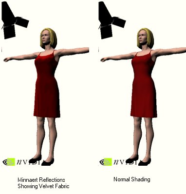
The left sample shows a woman with a velvet dress using Minnaert Reflections, a form of BRDF, the right picture is simply using normal shading algorithms. Unfortunately I had to scale the pictures down, but you can still just about see the difference in realism between the two.
Blinn Bump Mapping = True Reflective Bump Mapping
GeForce2 as well as ATi's Radeon are already able to do some really nice dot3 bump mapping, which requires a special texture, the normal map. This normal map gives each pixel of the surface (triangle) a new surface vector (normal), creating a 'geometrically non-existent but real looking' bumpy surface on a smooth triangle. The pixel rendering unit of GeForce2, also called NSR = 'NVIDIA Shading Rasterizer' is however unable to do a look-up in a cubic environment map to add reflection to the bumped surface.
GeForce3's Pixel Shader is finally able to do true reflective bump mapping, also known as Blinn bump mapping. After the Vertex Shader has done the per-vertex dot3 setup and supplied the Pixel Shader with basis vectors for the transform of the bump map, the Pixel Shader generates a reflection vector out of the normal and the eye vector which looks into a cubic environment map to create the reflection.
'Blinn bump mapping' is almost as realistic as it gets.
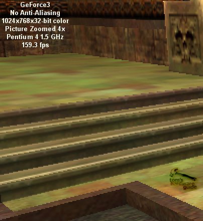
Anti-Aliasing - Removing The 'Jaggies'
Anti Aliasing has been a big topic in the 3D-scene last year when 3dfx put all its marketing force behind this single remarkable feature of Voodoo5. NVIDIA made the mistake of joining the anti aliasing world, providing a rather sad solution that was eating up 3D-performance like crazy. While 3dfx's T-buffer solution was certainly more efficient than NVIDIA's super sampling method, both performed too poorly to make it a really noteworthy feature. People who want high frame rates would never enable anti aliasing, simply because the performance impact is not acceptable.
If you should not know what the term 'Anti Aliasing' actually means I must ask you to please follow this link. I explained full scene anti aliasing in my GeForce2 article from April 2000.
The annoying stair step effect of the aliasing is typically seen in areas where two triangles intersect that don't have the same surface angle. Today you will never see the 'jaggies' within textures or on homogenous surfaces, because those areas are at least bilinear if not even trilinear filtered.
The only currently used trick to remove the stair step effect and smoothen those hard transitions is to use some kind of filtering method for complete frames. This could of course be seen as some major waste of effort, because most of the frame doesn't show any stair step effects and so it doesn't really require any filtering. However, since it is impossible to know where those hard transitions will actually appear, as several disappointing implementations of edge anti-aliasing have shown in the past, there is no choice but to filter the whole frame.
What does the term 'filtering' actually entail in 3D? To ensure that I don't blow this article totally out of proportion I will not go into the details of bilinear, LOD, trilinear and anisotropic filtering, but simply say this: filtering is achieved by involving more than one spot in the color calculation of a pixel. Simply said, filtering requires the involvement of neighboring 'structures' into the calculation of the color value of a pixel. This is what full scene anti-aliasing does.
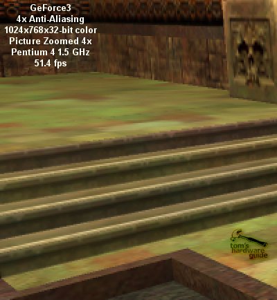
Now the difficult thing about filtering is that it requires the accuracy of a sub-pixel level to look any good. So far there are two ways known for anti-aliasing that achieve this sub-pixel level accuracy. The most commonly used technique is super-sampling. The idea behind super-sampling is very simple, but also very costly. The actual frame gets rendered to a resolution that is higher than the required screen resolution. In my example case of 4x super sampling the resolution is four times as high as the screen resolution, meaning it has twice the number of pixels in x as well as in y-direction. This rendering to 4x resolution has the effect that each pixel on the screen is initially represented by four pixels in the back buffer, each being of quarter size of the screen pixel. This way sub-pixel level is reached and the filtering of those four pixels generates the anti-aliased screen pixel. The result looks good, but the poor 3D-chip has to render four times the screen resolution, which costs a huge amount of fill rate, leading to rather bad 3D-performance. Due to the filtering stage, super-sampling anti-aliasing provides even lower frame rates than what would be achieved if you'd run the game at 4x the resolution without anti-aliasing. Super-sampling AA is today used by all the GeForce chips as well as ATi's Radeon. You can only use it at resolutions up to 800x600 (in case of 4x AA the frame is rendered to 1600x1200!), because otherwise games are pretty much unplayable.
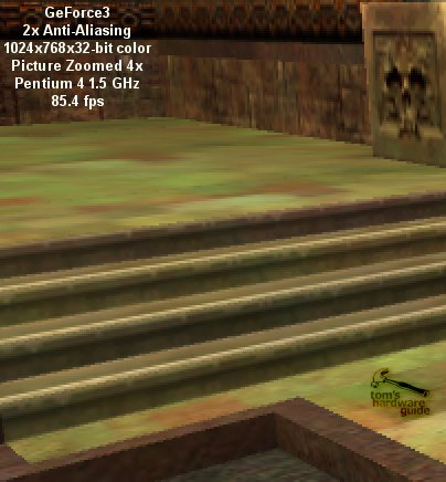
The alternative to super sampling is multi sampling. This is the technique used by GeForce3, but a special version of it has previously been used by 3dfx. The idea of multi-sampling AA is to render multiple samples of a frame, combining them at sub-pixel level and then filter those sub-pixels to achieve anti-aliasing. Theoretically there isn't any fill rate benefit of multi-sampling AA, because 4x AA would also require that 4 sub-pixels get rendered for each final pixel, having the same requirements in terms of fill rate as super-sampling. However, multi-sampling is a bit less expensive in terms of performance than super-sampling, because it doesn't waste any energy into the useless creation of detail for higher resolution rendering.
The reason why 3dfx's implementation was superior to NVIDIA's super-sampling method in terms of performance is because Voodoo5 used some slightly strange and proprietary way to filter the sub-pixel samples. The filtering wasn't done with any kind of computation, but the samples were overlaid at sub-pixel level within the RAMDAC-unit of Voodoo5. This also explains why it was impossible to take screen shots of it. The filtered frame was never represented anywhere in the frame buffer memory. One can think about this weird technology what one wants, Voodoo5 benefited from the missing performance impact of the filtering stage and was therefore able to produce higher frame rates, while giving respectable anti-aliasing results on the screen.
GeForce3's New High-Resolution Anti-Aliasing (HRAA)
NVIDIA's new GeForce3 is also using multi-sampling anti-aliasing and different to the previous GeForce chips it has the whole technology for this anti-aliasing method hardwired inside. GeForce3 is also creating multiple samples of a frame, storing them in a certain area of the frame buffer and before the frame gets flipped the HRAA-engine filters the samples and stores the result in the back buffer. This makes the anti-aliased frame fully software accessible and allows screen shots.
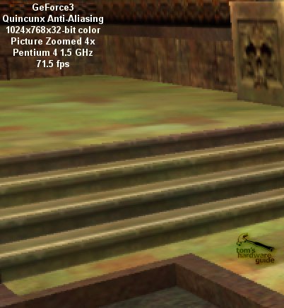
Besides the normal AA-modes of 2x and 4x, GeForce3 is also offering a special AA-mode with the hilarious name 'Quincunx'. What a name! 'Quincunx' doesn't stand for some strange birth defect, but for a very nifty super-sampling trick. Quincunx generates the final anti-aliased pixel by filtering 5 pixels of - and that's the trick - only TWO samples. The effect of 'Quincunx' is an anti-aliasing effect that comes close to the quality of 4x AA, but it only requires the generation of two samples. 'Quincunx' is the reason why GeForce is indeed able to provide excellent AA-performance with good AA-quality. Here is how it works:
The 3D-scene is rendered normally, but the Pixel Shader is storing each pixel twice in two different locations of the frame buffer. This doesn't cost more rendering power than the rendering without AA, but twice the memory bandwidth of the pixel write operation at the end of the pixel rendering process.
By the time the last pixel of the frame has been rendered, the HRAA-engine of GeForce3 virtually shifts the one sample buffer half a pixel in x and y direction. This has the effect that each pixel of the 'first' sample is surrounded by four pixels of the second sample that are 1/ SQR(2) pixel away from it in diagonal direction. The HRAA-engine filters over those five pixels to create the anti-aliased pixel. As already said, the performance of this Quincunx-AA is excellent and the quality very good.
Here are some samples I took in Quake3 Arena, High Quality, 1024x768:
Hello Voodoo5 - GeForce3's Other Multi-Sampling Features
The straightforward implantation of multi-sampling into GeForce3 enables more than high performing anti-aliasing. As already said, 3dfx's Voodoo5 was also using multi-sampling and so it doesn't surprise that GeForce3 is now listing all the special features that we know from Voodoo5 already. Alternative to the per-vertex motion-blur mentioned above, GeForce3 can also use multi-sampling to create this effect. The other typical multi-sampling effect is 'depth-of-field', which simulates the focusing of camera optics, blurring either the area far away or the area close up, depending on the focus.
Almost 18 months have passed since NVIDIA released the first 3D-chip with integrated transform and lighting (GPU). In the beginning it looked as if that didn't have any impact on the game developers at all, but finally 3D-games started to take advantage of integrated T&L and now the number of triangles used per frame is continuously growing. NVIDIA should be pleased, because it was asking for more triangles, more geometry detail, or more vertices.
In the past, most of the AGP-bandwidth was used for texture loads. 1x AGP was finally becoming too slow and 2x AGP became state of the art. Today, texture compression algorithms are used, so that texture transport is not really the big problem anymore for today's 4x AGP cards. This does not mean however, that the bandwidth of 4xAGP isn't required. In fact, 4xAGP is already becoming a serious bottleneck, because the increasing geometric detail requires more and more vertex transfers and will finally saturate the AGP with huge amounts of vertex traffic to the 'GPU'.
Another problem is that today's game developers are somewhat stressed creating all those nifty objects with their high geometric detail. While buildings and characters may still be a lot of fun to design, landscape design is a rather boring task if you've got to incorporate ten thousands of triangles for high detail. Today there are a lot of tools that do this job for the developer, but why should these highly detailed objects be transferred vertex by vertex across the AGP if these tools are able to create complex 3D objects out of only a few parameters in the first place? Wouldn't it be wiser to transfer the parameters and incorporate those tools into the GPU?
Then there is another annoying fact. Today's 3D-objects are always represented by the same amount of vertices, regardless if they are close to the viewport or far away and hardly visible. Many triangles of these objects are just as small or even smaller than one pixel. The unnecessary detail of those objects is saturating the AGP and the small triangles pose a serious performance problem to the rendering pipeline.
Microsoft's latest approach to tackle those problems is hidden behind the term 'higher order surfaces'. The idea is to describe curved surfaces only with some control points. A curve or surface that is only defined by some control points or control vertices and a certain function/formula that describes the geometry of the actual shape is called 'Spline'.
GeForce3 is able to accept control points and functions instead of triangles. Once the control points and the function are transferred to GeFroce3, it is able to create triangles out of it, which are then fed to the vertex shader. This process of making triangles out of splines is called 'tessellation'. In the past this job had to be executed by the CPU.
The advantages of higher order surfaces are clear:
- The transfer of splines instead of a large number of vertices across the AGP is able to reduce bandwidth requirements and makes AGP less of a bottleneck.
- Developers can create realistic looking objects with special tools that create the kind of higher order surfaces DirectX8 and GeForce3 understands without having to fiddle with thousands of triangles.
- 3D-objects could use only the amount of triangles they require in a certain situation, ensuring that the level of detail remains the same. This means that a car that is close in front of the scene could consist of many more triangles than the same car somewhere far behind in a corner of a 3D-scene. This mechanism is called 'adaptive tessellation'.
There is of course also a downside, even though NVIDIA's marketing papers don't talk about it:
- There are lots of different tools that can create higher order surfaces, but GeForce3 can use only certain forms.
- NVIDIA claims that collision detection is 'straightforward'. If you think again however, you will realize that a game will have a rather hard time doing collision detection if the object is not represented by actual triangles. The CPU will have to calculate the actual surface of an object each time it does the collision detection, which costs a lot of CPU horsepower.
- Finally there is the question how well GeForce3 actually performs if it has to do the tessellation. NVIDIA has not supplied an answer to this one yet.
- Not every game developer likes the idea of higher order surfaces, which e.g. require a change of the 3D-engine. John Carmack is probably the most prominent person that has reservations against it.
The idea of higher order surfaces sounds great. However, it actually sounds too good to be true. I feel as if this feature was merely implemented into GeForce3 to ensure its full DirectX8 compatibility. We will see if the performance of games with higher order surfaces will be acceptable on GeForce3. First of all we need a game that uses it.
GeForce3's Lightspeed Memory Architecture
I kept the IMHO biggest goody of GeForce3 until last. It is part of the so-called 'Lightspeed Memory Architecture' of NVIDIA's new flagship GPU and might receive a lot of attention beyond the 3D scene.
One of the most important factors for the performance of a 3D-controller is its actual memory performance, as we at Tom's Hardware guide have pointed out on numerous occasions. Typically the high fill rate claims of 3D-chip makers can never be fulfilled because the memory bandwidth required for those fill rate numbers is simply not available to the chip. This situation becomes particularly evident in 32-bit color rendering situations.
The memory bandwidth numbers listed in the specifications of graphics card are always peak performance numbers and have very little to do with the real world. People who followed the RDRAM-situation with Pentium III last year will remember that high peek bandwidth doesn't have to translate into high performance at all. Pentium III systems with the high-bandwidth RDRAM were easily beaten by other systems with PC133 memory, mainly because the latency of RDRAM is too big, making it react slowly to accesses to a different memory area than the previous addressed one.
For 3D-rendering, memory latency and granularity can become more important than peek bandwidth, because the pixel rendering is often requiring reads from memory areas that are far apart from each other. Each time a page needs to be closed and another one opened, wasting valuable time. I already discussed the fact that recently the geometric detail of scenes is increasing, leading to a growing number of triangles per frame. An increased number of triangles does automatically lead to a smaller average size of triangles as well. Detailed objects far away in the back of the scene can contain triangles that are just one pixel in size. The smaller the triangle the less effective are common memory controllers. This is for once because a new page might need to be opened just for one read/write operation. The next triangle could be just as small but in a different screen area, which would require another page open/close process that reduces the actual memory bandwidth to only a fraction of the peak bandwidth that can only be achieved with sequential reads (bursts). The second problem is the fact that common DDR-SDRAM controllers can transfer data only in 256-bit = 32 byte chunks. If a triangle is only one pixel in size it requires a memory access of 32-byte although only 8 bytes (32-bit color plus 32-bit Z) are required. 75% of the memory bandwidth would be completely wasted.
GeForce3's Crossbar Memory Controller
NVIDIA decided to tackle this increasing problem in GeForce3. The task was to reduce latency and improve granularity. The result is GeForce3's brand new crossbar memory controller.
The crossbar memory controller of GeForce3 consists of four single 64-bit wide memory sub-controllers. Those sub-controllers interact with each other to address arbitration problems and make memory access as efficient as possible. The excellent design of this memory controller is able to attack both problems, latency as well as granularity. With 64-bits the granularity of each sub-controller is much finer than the 256-bit wide read/write accesses of common DDR-SDRAM controllers. The four different sub-controllers can all have open pages, which cuts the average latency down to 25%. For me personally, the memory controller is the real gem within GeForce3, because it is useful with any kind of 3D-application, regardless if brand new or ages old. Owners of GeForce3 may not be able to benefit from the vertex shader, the pixel shader or higher oder surfaces, but they will definitely be able to appreciate the crossbar memory controller. People who complain that GeForce3's theoretical peak fill rate is 'only' 800 Mpixel/s versus 1,000 Mpixel/s of GeForce2 Ultra have still not understood how it works. The high effinciency of GeForce3's memory controller will ensure that it beats GeForce2 Ultra in 99% of the cases. Regardless if the fill rate bean counters will ever understand that or not.
I wonder if companies with a really bad memory controller history, as e.g. VIA Technologies, couldn't ask NVIDIA to give them a few tips on how to implement a crossbar memory controller. There is no doubt that microprocessors could benefit from this technology as well. Rambus Inc. could use this technology to tackle the latency penalty of RDRAM. In this case I hope that NVIDIA has applied for a patent early enough, because otherwise Rambus may follow its tradition, copy NVIDIA's design, patent it and then sue NVIDIA. But jokes aside, NVIDIA is known to work on a core logic (=chipset) anyway and, who knows, the crossbar memory controller might soon enough find its way on motherboards with NVIDIA chipsets. Intel, and VIA beware!
GeForce3's Approach To Tackle The Z-Buffer - HyperZ Made In Sunnyvale
The second part of GeForce3's 'Lightspeed Memory Architecture' is an implementation to reduce Z-buffer reads. I have described the high impact of z-buffer reads and the waste of fill rate as well as memory bandwidth for hidden pixels or triangles in my article about ATi's Radeon256 already. Please have a look at this page if you should not be familiar with the problem.
NVIDIA has finally seen the same signs that made ATi design their HyperZ-technology and now GeForce3 receives a similar feature set as already found in ATi's Radeon256.
The frame buffer area that is most accessed by a 3D-chip is the z-buffer. The reason is fairly simple. There are only few memory accesses up to the triangle setup and rasterizer stage of the 3D-pipeline. The rasterizer stage is also defining the 'birth' of the z-buffer. All previous stages are handling vertices, which carry their z-coordinate along with them. The triangle setup/rasterizer calculates the color values, the texture coordinates and the z-value for each pixel of a triangle and sends it to the rendering pipeline.
The first thing the pixel render engine (in GeForce3's case the 'Pixel Shader') does after it received a new pixel is read the z-buffer. This stage is required because the pixel render engine needs to know if there is already another pixel at the x/y-coordinate of the new pixel and if this 'older' pixel is actually lying in front of it. If the z-value at this coordinate is zero or less than the z-value of the new pixel, it goes through the pixel-rendering engine. When the pixel is ready rendered the color value is written to the back buffer and the z-value of this pixel is stored in the z-buffer. Now the next pixel is fetched from the rasterizer and the game begins anew. You can see that per triangle-pixel the z-buffer is accessed at least once for a read operation and per displayed pixel the z-buffer is accessed once more. No other buffer gets hit that often. You can imagine that a reduction of z-buffer accesses could save highly valuable memory bandwidth.
The first way that NVIDIA uses to reduce the amount of required z-buffer bandwidth is to implement a (thankfully) lossless compression of the z-buffer. ATi's Radeon256 is doing the same since July 2000. NVIDIA speaks of a lossless 4:1 compression, which could theoretically reduce the impact of z-buffer accesses on the memory bandwidth by already 75%. Lossless 4:1 compression is not as simple however. Try it by yourself. Create a text file with 'hello world' and zip it. Zip/unzip is also a lossless compression of files. You will see that the compression rate increases as the size of the text file increases. This goes only up to a certain level, but it is a fact that a text file that only contains the letter 'h' will certainly not get a high compression ratio. The same is valid for the z-buffer compression of GeForce3 and Radeon256. Neither of the two will read or write the whole z-buffer when one address is accessed, but one z-buffer value alone can obviously not be compressed 4:1 as well. It is most likely that GeForce3 is compressing sub-units of the z-buffer that are cached on the GeForce3 chip. Radeon256 is using 8x8 = 64 byte sub units.
Visibility Subsystem: Z Occlusion Culling
What's hidden behind this fancy name is NVIDIA's version of Radeon's Hierarchical-Z plus advancement. The Z occlusion Culling is special procedure between the stages of the triangle setup/rasterizer and the Pixel Shaders to determine if a pixel will be hidden behind an earlier rendered pixel or not. If the Z occlusion culling should determine that the pixel is hidden it will directly be discarded and it won't enter the pixel shader, thus saving the initial z-buffer read of the pixel-rendering pipeline.
The technology behind this process is most likely, just as in Radeon's case, a hierarchical Z-cache that covers a certain part of the screen. This cache can quickly read one of the above-mentioned 4:1 compressed sub-units of the z-buffer and probably represent the z-buffer in blocks of pixels, simply storing the lowest z-value found in this block. When the triangle setup/rasterizer is spitting out a pixel, the z occlusion culling will compare its z-value with the value stored for the according pixel block. If the z-value of the pixel is clearly lower than the z-value of the pixel block representation, the pixel will be discarded. If the z-value is larger than the block value it will be sent to the pixel shader.
NVIDIA's advance over ATi's Hierarchical-Z is what they call 'Occlusion Query'. The 3D-application requests GeForce3 to check the z-values of a special area (which will most certainly be of the same size as the hierarchical z-cache). If it turns out that the triangles in this area are hidden behind an object that has already been rendered all triangles of that area will be discarded.
It has to be said that the efficiency of this z occlusion culling or hierarchical-z method is depending on the 3D-application. The best effects can be seen if the 3D-application is sorting its scene objects before it sends them one by one to the 3D-chip. The ideal case is if the application is first sending the objects in the front of the scene and then the objects further behind. It avoids that pixels of hidden objects in the background of the scene are rendered first and later overwritten by pixels of objects in front of them. The worst case would be if the application would sort the objects back-to-front (which no application would deliberately do). Then even Z Occlusion Culling or Hierarchical-Z couldn't help a bit. In average the 3D-objects are drawn in random succession, leading to a depth complexity of 2 - 3.5. In this case GeForce3's Z Occlusion Culling can be of great use.
Could there possibly be a conclusion without any hard benchmark data? Not in case of a high-end 3D-chip. However, I can certainly offer a summary and a personal opinion about GeForce3's technology.
First of all I would like to say that this article is not just incidentally the longest article I have ever written. If you take in consideration that it doesn't even include one benchmark graph, you will get an idea how huge this article really is. The amount of technology provided by NVIDIA's new GeForce3, the Xbox predecessor chip, is simply overwhelming. This processor doesn't 'just' have 57 million transistors. They have actually been USED! If it is the Vertex Shader, the Pixel Shader, the High Resolution Anti Aliasing, the Crossbar Memory Controller or the Z Occlusion Culling, this chip has been STUFFED with high-tech! Let me now take a deep breath and go through the new technologies one by one.
I have to say that I love this feature, because it offers a tremendous amount of possibilities. My personal favorite is the reflection and refraction demo, which really shows how close 3D rendering can get to reality. However (with Tom there's always a 'however!'), it remains to be seen if the single vertex shader pipeline of GeForce3 will be performing well enough to make games with all those great features playable and not just eye candy. Right now, the maximal amount of vertex instructions is limited to 128 and although the vertex shader is strictly scalar, NVIDIA has decided to supply GeForce3 with only a single pipeline. Xbox will most likely have two pipelines. I can't say it often enough, I hope that the vertex shader will perform well enough.
This unit seems to be a straightforward development of previous pixel rendering units. I don't know if the programmability of it will be good enough to set it far apart from previous pixel renderers. The most important feature of the pixel shader is that the vertex shader drives it. From that point of view it makes perfect sense. One couldn't live without the other. I am less concerned about the rendering performance of the pixel shader, even though the theoretical peak fill rate is less than that of GeForce2 Ultra. The new memory controller will make sure that GeForce3 will beat GeForce2 Ultra by quite a long shot.
This feature - excuse me - kicks ass! I have tested it numerous times here and it works, performs well and looks great. I never used to be a big fan of anti aliasing so far, even though my usual system is equipped with a GeForce2 Ultra. The performance with anti-aliasing enabled was too poor that the effect would have been worth it. With GeForce3 anti-aliasing has become reality. 1024x768x32 with Quincunx-AA enabled at more than 70 fps is more than satisfying and looks excellent. I only wonder if NVIDIA shouldn't have changed the name of 'Quincunx'. The Internet will soon rename it to something else.
I don't know what to think about this feature. In all honesty, I don't really think much of it, as you probably already noticed. The idea behind it is excellent, but I doubt that the implementation is good enough right now. I also wonder about its performance.
What can I say? I love it! Finally somebody made sense and put a high-end memory interface into a PC. Intel, Rambus, VIA and Co. should take this as a lesson. If they won't wake up soon NVIDIA will have the chance to enter the core-logic market big time. Big Kudos to NVIDIA for this implementation! That's what I want to see!
I remember how much I welcomed ATi's Hyper-Z and I almost feel a bit unfair towards NVIDIA, that I can't' get all exited up about their solution. It was certainly the wisest thing to implement a technology that can live up to ATi's Hyper-Z, but it wasn't the first and thus my enthusiasm is limited. Let me still say "Well done NVIDIA, you did the right thing!"
It is too bad that the current drivers for GeForce3 are still too flaky to use them for a good benchmark session. This doesn't mean that GeForce3 is crashing, but there are a few applications where it shows some strange artifacts right now, which is reason enough to wait for flawless drivers instead of pushing out some semi-meaningless benchmark numbers. What I have tested ran FAST. The already mentioned Quincunx anti-aliasing performs very well, Quake 3 reaches excellent numbers, especially at high resolutions and true color. This is of course no surprise if you take the crossbar memory controller into consideration. After all it was always the memory bandwidth that held the GeForce chips back. Of course I was unable to test the vertex shader performance, since there isn't any software available that would let me. Results of 3DMark if 2000 or the upcoming 2001 have never had much of a meaning to me and I doubt if this will change once it can benchmark the vertex shader. After all, what would you compare those results to?
GeForce3 is loaded with high-tech features that will excite every techie on the planet. However, most features won't be very beneficial as long as there isn't any software that takes advantage of them. We know how long it took until integrated T&L became worthwhile, so I don't expect any miracles with software titles that support the vertex or pixel shader as well. The two features that make GeForce3 worth a look right now are the impressive high-resolution anti-aliasing and the high-tech crossbar memory controller. Other than that GeForce3 could maybe be seen as an excellent platform for Xbox developers.