Cylinders
Click On Thumbnails To Enlarge
NEW 10/06/02
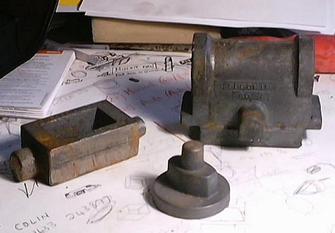
The cylinders are cast iron and were bought as castings. Here's a picture of the main casting along with the steamchest and cylinder cover castings.
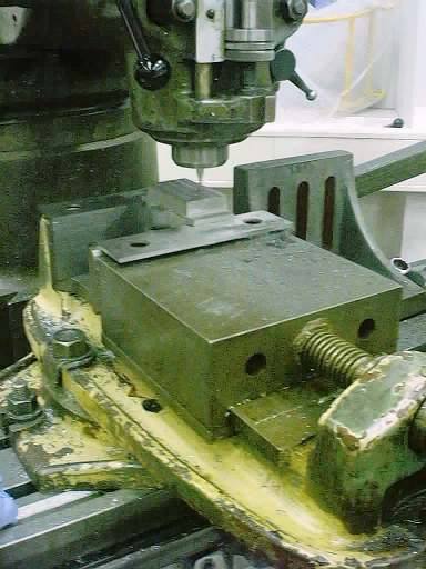
As the unimat isn't big enough to machine the castings we managed to get a couple of days on a Bridgeport mill. As I type this the first day of work is complete and one and a half castings are now machined. Here's a picture of one of the castings partly machined setup in the machine vice. The valve face is uppermost in the picture.
NEW 21/06/02
Once we had machined the outside of the cylinders it was time to turn our attention to the ports. Our original plan had been to EDM (spark erode) the ports out. We got hold of some copper bar for this. However when it came to making the electrode it became obvious that a lot more work than we anticipated would be required.
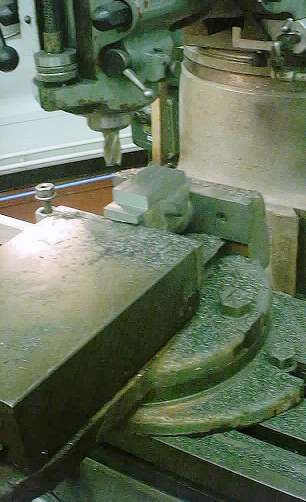
We decided that a better alternative would be to simply mill the ports. This was made a lot easier as the milling machine we were using were fitted with Digital read outs (DRO's). With two mills going I churned out the basic machined castings while Alastair milled the ports. Here's a picture of the ports being milled.
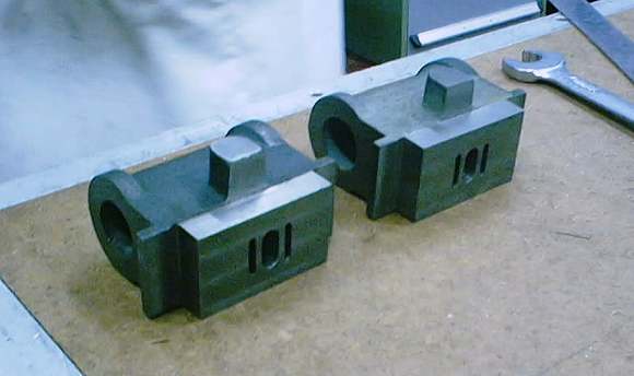
And here's a pic of a pair of part complete cylinders.
The next challenge was to bore the cylinders. We decide to try and do this in the mill. The cylinders were held in the machine vice and centre of the bore accurately found from the valve face. We then put a boring head in the spindle and 'had a go'. The cored hole through the casting was not concentric with the required position of the bore. This meant that the first few cuts through the hard skin were intermittent. This immediately 'killed' the tool in the boring bar.
Time for a re-think. We decided that there were a few possible solutions. The first was to bore in the lathe, the second was to bore in the lathe and ream and the third was to run a slot drill through the hole and then ream to finish size. We decided to use the best of all the options. So we first used an end mill to make a shallow counter bore in the end of the block. This could then be used to clock the cylinders up in the 4 Jaw of the lathe.
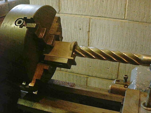
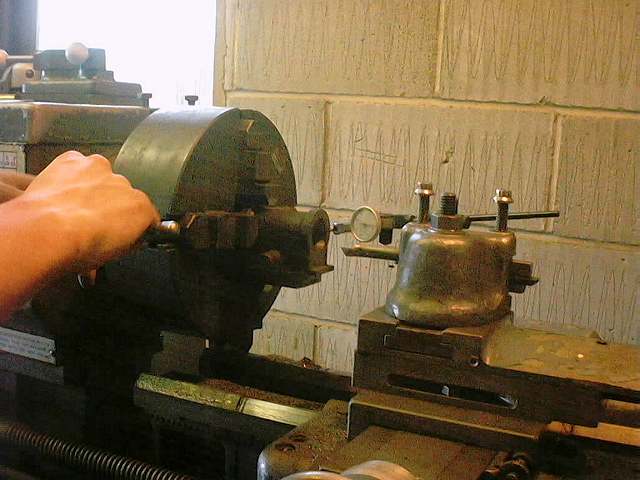
Here's a view of the a cylinder being 'clocked up'.
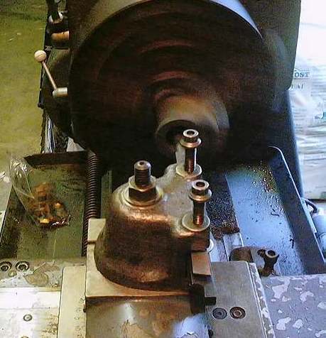
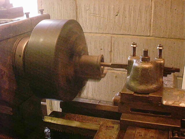
And a couple of views of the boring process - this truly was like it's namesake taking about 2 hours per cylinder to bore to size !
Once we had bored almost to size we finished the bores by reaming. This was where the backgear on the lathe was extremely useful allowing it to run at 38 rpm!