Valvegear
Click On Thumbnails To Enlarge
The valve gear is Stephenson link with launch-type links and centre suspension. The die-block is connected to the valve through the valve spindle. The pair of valve spindles pass through a set of bushes mounted on the motion plate. Also fitted to the motion plate is a feedpump. The motion is imparted to the expansion link by a set of eccentrics fitted to axles. There are a pair of eccentrics and rods fitted to each expansion link, with each valve having it's own motion. To allow adjustment of the valve timing the valve spindles are fitted with turnbuckle adjusters.
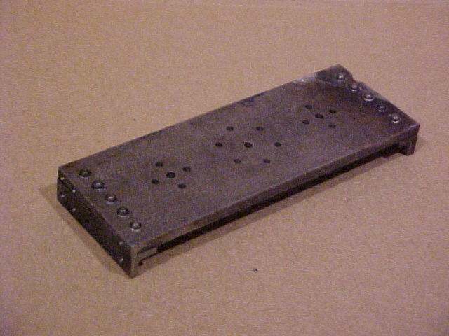
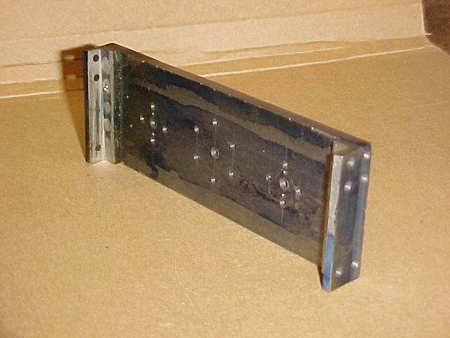
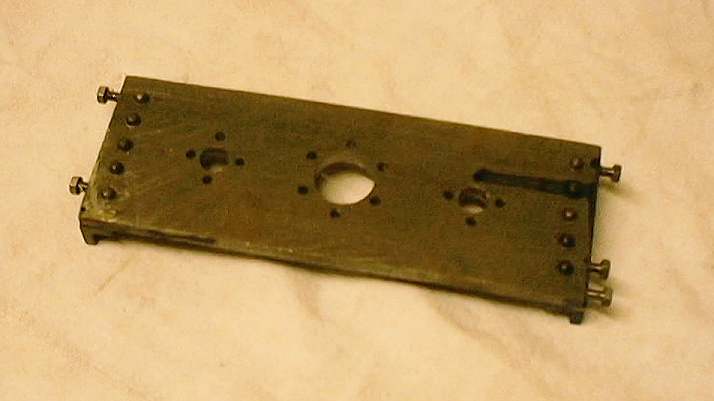
I began work on the valvegear by manufacturing the motion plate. This is quite a tricky thing to make requiring a piece of 3/16" plate to be tapped from the end! A couple of broken taps and a bodged repair later I had a pair of motion plates.
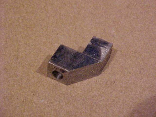
For some components it essential that they are made in a certain order. However some parts are not dependant on the sequence so they can be made in any order. This is extremely useful where the lathe is setup for milling. One such part is one of the valve spindle connectors.
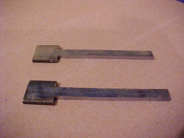
Another part that could be made was the feedpump rod. This was roughly cut from a piece of strip and then (so I could work off all that xmas turkey!) hand filed them to shape. The pictures below show the the partly completed rod.
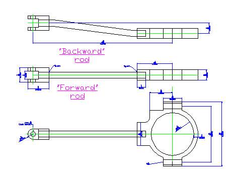
One of our biggest pains in the a**e during building Conway is our lack of any large milling facilities (thanks to Carl for the bits he's done on his miller for us!). It seemed to rather pointless to go out and spend a lot of money on a large miller when the majority of the work could be done on the unimat. One set of parts though that set my head scratching were the eccentric rods. Have a look at the drawing below and you'll see the problem - these need to be milled from solid (cos I ain't got any welding facilities!) - the idea of a few weeks of clamping, re-clamping and numerous milling cutters late didn't appeal.
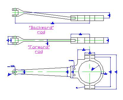
Then, there I was one day sat in a lecture and it suddenly hit me - why do the rods need to be that shape. The main reason is so they look nice. However I remembered seeing a picture of a loco with the eccentric rods being made of rod with a bolting plate on one end. So I knocked up the drawings and amazingly it would work. Thread the eccentric straps. Make a threaded forked end - screw it all together and you even get some adjustment to boot - and all this with minimal milling work. The drawing below shows the re-designed rods.
I actually finally got round to opening out the holes in the motion plate. The smaller holes at the sides are for the guides for the valve spindles and the large hole in the centre is for the feedpump (see the pic on the castings page)
NEW 04/06/2002
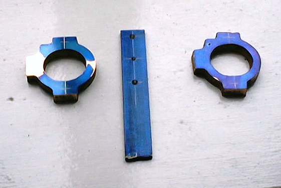
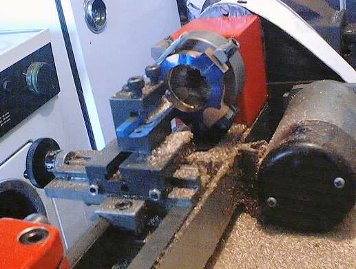
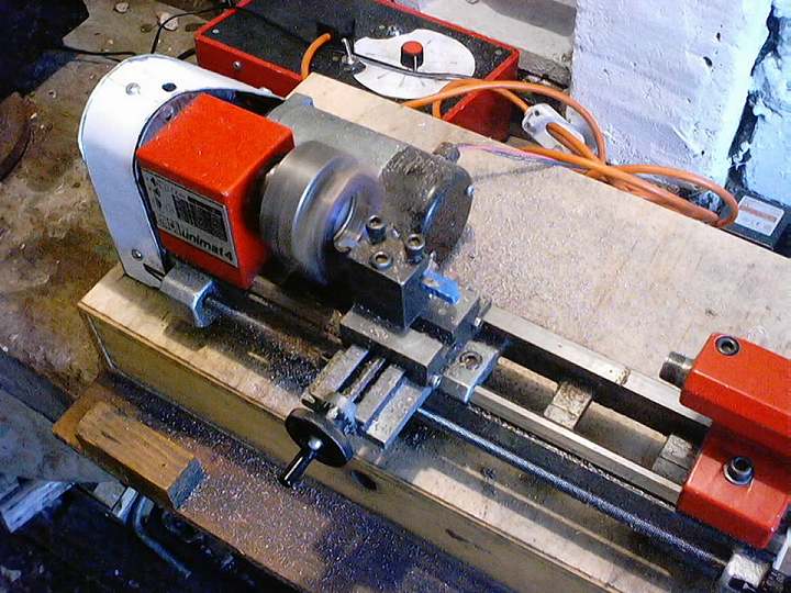
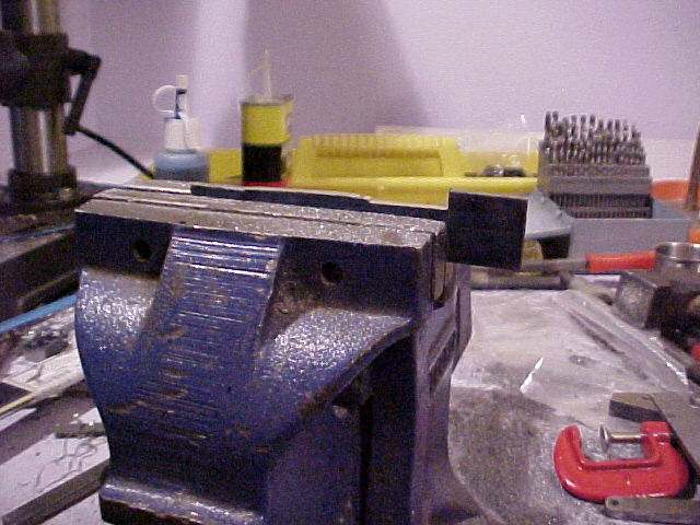
An important part of the valvegear is the eccentrics and their straps. I've left Alastair to get on the with eccentrics while I attack the straps. The straps started life as a set of castings. These were then faced to the correct thickness in the 4-jaw and then bored to approximately the correct diameter.
There are 9 straps in total per engine - 8 for valvegear and one for the feedpump. As there are so many of them I made a simple jig to get them all bored similarly. The jig and a couple of the castings are shown below along with some pictures of the boring operation :-