Frames
Click On Thumbnails To Enlarge
Work on the frames began just before we finished university for our summer recess in 2001. Initially we investigated buying the plate and doing all the shaping work ourselves - this would have been a lot of work so we looked around and found a company that would supply and water jet cut the profile including all the holes. Unfortunately I had a few problems with this company and definitely won't be using them again!!! Finally the plate arrived and construction could start.
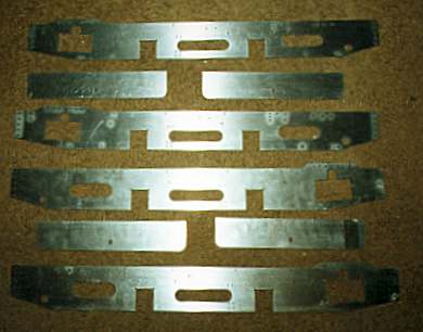
Here's a picture of the frame plate as delivered. Unfortunately taking a picture of bms plate isn't the easiest thing to my amateur photography skills!!!
The next step was to cut all the pieces of angle that would be riveted to the buffer beams through which the bolts passed to secure them to the frames. These were all made from brass angle.
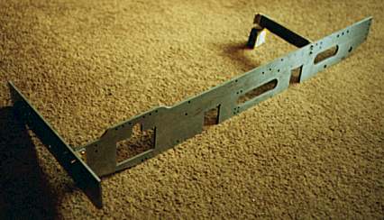
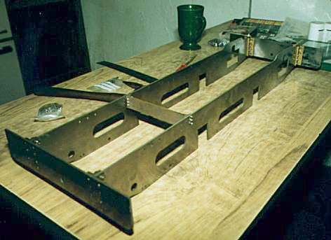
Here's a view of the first test assembly of the frames, rivets have been pushed through the holes. Note the already constructed frame stretcher near the rear of the loco - riveting practice!!
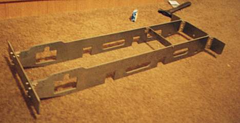
As more of the angles were drilled ready for riveting I performed another test assembly (just because i wanted to see what they were going to look like!!).
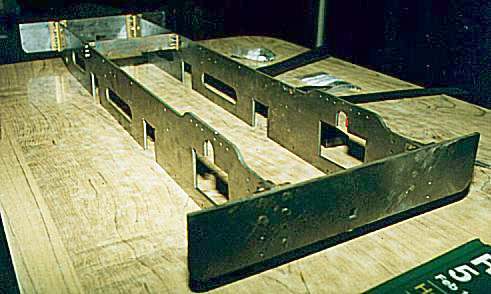
The moment of truth - the first set of frames being assembled. At this point the dumb buffers are missing (I was waiting for the material to be delivered) but apart from this all other riveting was complete and all the bolts fitted.
Another view of the frames - this time from the rear. Notice the kitchen table assembly bay with the obligatory cup of tea in the background!
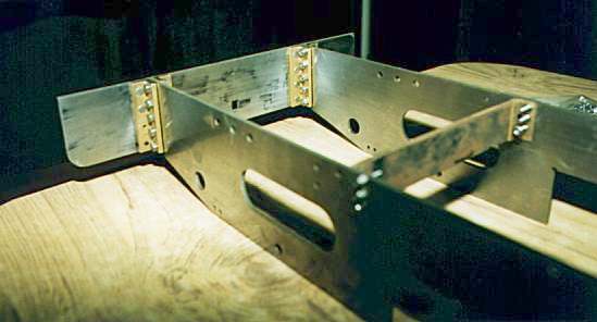
A close-up of the rear of the loco. As can be seen each frame plate fits between a pair of brass angle riveted to the buffer beam.
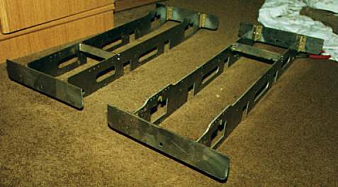
A marvelous site - a pair of assembled and trued up frames.
Once the material arrived the dumb buffers were produced and riveted in situ along with some supporting angles for the running boards.
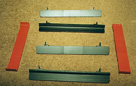
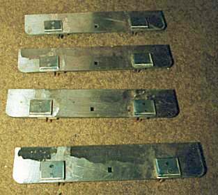
A view of some of the components for the frames. The two red parts on either side are frame stretchers (one per engine) as seen in some of the earlier pictures. The other components are 'safety angles' or as I prefer to call them crash beams! In the event of a derailment these should hit the railhead and slide along the top to help minimize any damage to brake gear and other low slung items.