Assembly
Click On Thumbnails To Enlarge
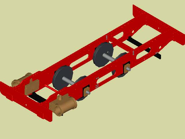
During the assembly of the loco I decided that it would be quite useful to create a 3-dimensional model of the loco in AutoCAD and make sure that everything fits. I still haven't finished it yet but the image below shows the major chassis components in situ.
The assembly process started with the assembly of the frame plates
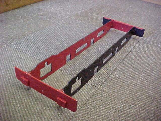
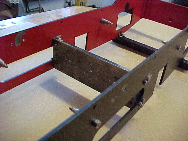
The image below clearly shows the safety angles (crash beams) in place.
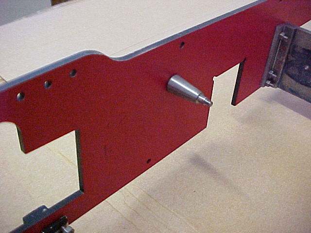
As progress is made each part is gradually 'hung' on the engine. The picture below shows the brakepins fitted to the frames.
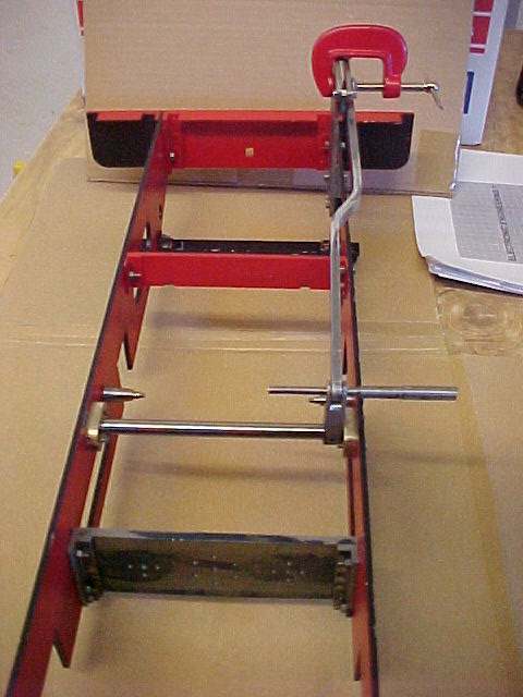
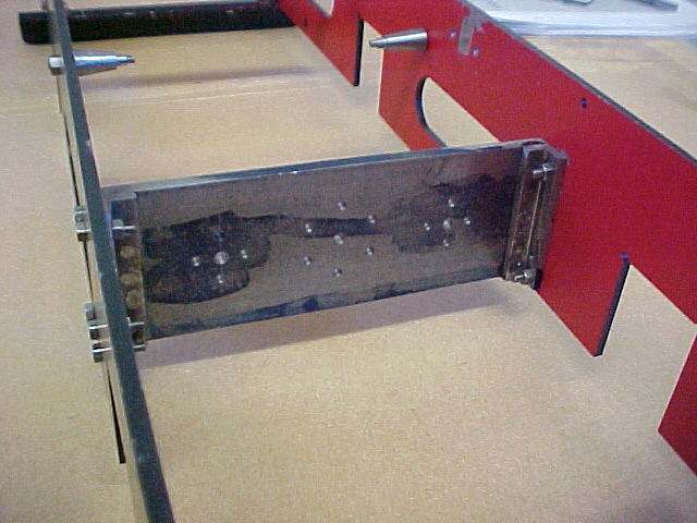
And once the motion plate was completed this was test fitted. Note that the hole in the centre for the feedpump and the two holes either side of this for the valve spindles have yet to be opened out to full size.
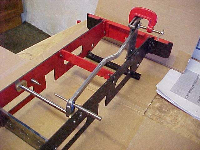
The next parts to be test fitted were the weighshaft and it's associated bearings along with the reversing arm.
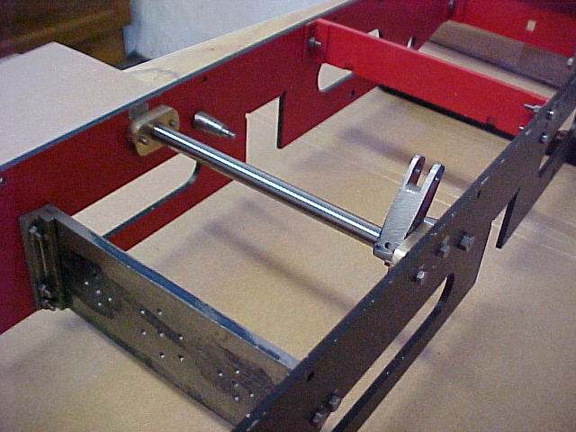
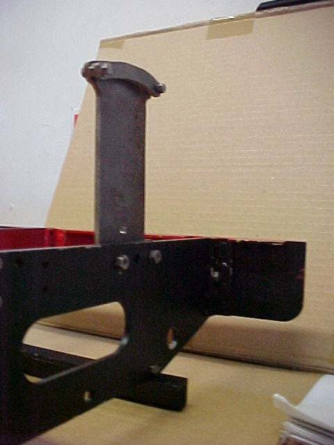
The reverser stand was bolted to the frame and then the reach rod was temporarily fitted in place to check that the step in the rod was sufficient. As can be seen a temporary pin was fitted at one end while the other end was clamped in place with a suitable spacer.