Reversing Gear
Click On Thumbnails To Enlarge
The reversing gear consists of a lever reverse in the cab, connected to the weighshaft via the reach rod. Four lifting arms are fitted to the weighshaft. To each one of these arms is fitted a link which attaches to the expansion link.
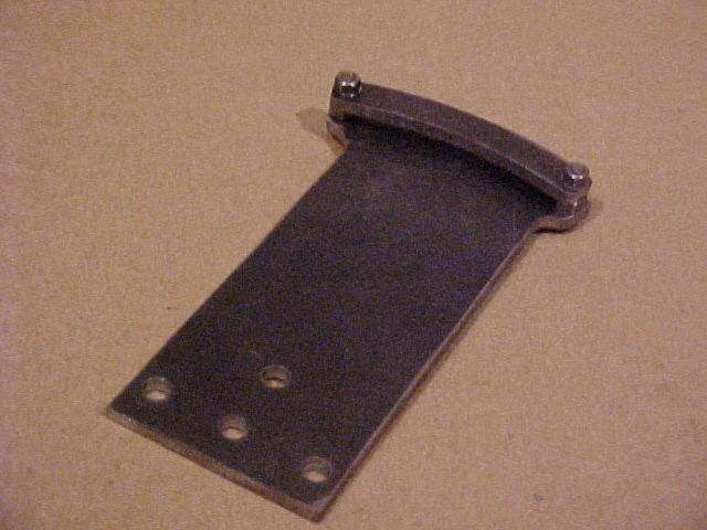
Work on the reversing gear started with the manufacture of the reverser stand and motion plate. From my CAD drawings I produced a template for the parts which included a set of centre points so that I could chain drill around the shape and then file it to the finished profile. Two pieces of 1/8" thick plate were cut, the template was glued onto one piece, and then I accurately drilled the holes that were required. This allowed me to bolt the two pieces together and then chain drill both profiles in one go.
After about 6 hours of drilling and filing they were complete - phew!
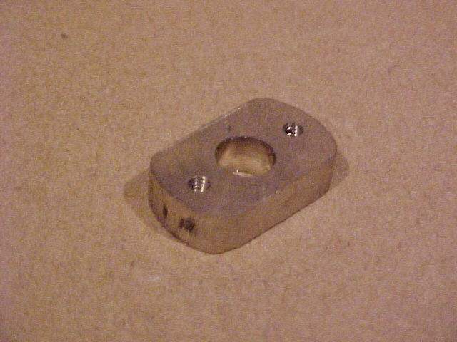
To hold the weighshaft a pair of bearings had to be produced. In the drawings they are shown to be lozenge shaped. There didn't seem to be any reason that they must be this shape so I decided to make them in a slightly easier way. Alistair found a piece of phosphor bronze bar kicking around that was perfect. So into the unimat it went. It was bored to size, then split and finally faced. I then held the pieces by their front faces and machined the top and bottom off. A quick touch with a file and I think they look quite nice. To finish off they were drilled and tapped 4ba for fitting.

The next step was to manufacture the reversing arm. This was a simple piece of strip cut to length and faced in the lathe. The holes were then drilled and finally the end was slotted to accept the reach rod.
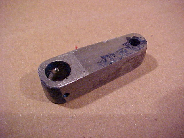
When I cam to make the reach rod I deviated slightly from the drawings. The drawing shows the rod to be waisted along almost it's entire length. This seemed a bit too much like hard work (yes I am just lazy!). Therefore I left the rod the same size throughout but I had to chamfer the slot inside the reversing arm.

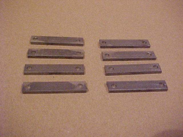
I then moved on to making the lifting arms and links and these were initially cut to size and faced to length in the unimat then drilled to size (or for reaming). The left hand picture shows the links drilled and ready for shaping and reaming. The right hand picture shows the lifting arms drilled and ready for slotting and reaming followed by final shaping.
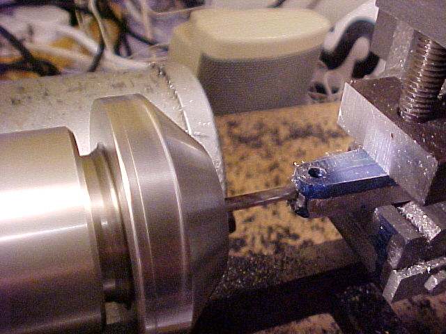
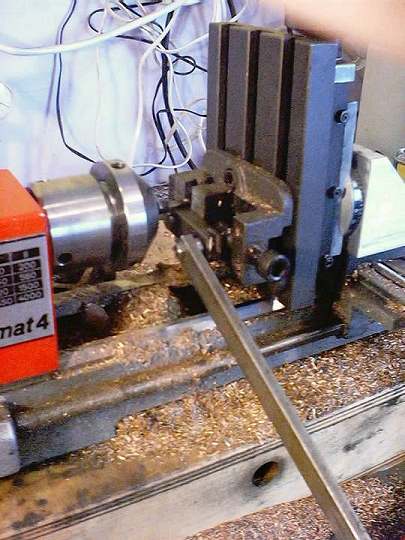
I decided to try a little experiment to shape the lifting arms. WARNING - this is certainly not the safest way to machine such parts and only people as stupid and brave as me would try it! Anyway with the legal disclaimer over what I decided to do was clamp a piece of rod in the machine vice. This piece of rod was a good fit in one of the holes in the arm. I then made a pin to fit in the other hole and bolted this to a long piece of flat bar. Can you guess what it is yet ???? Then carefully bringing the milling cutter up against the arm. I simply rotated the arm against the cutter using the piece of rod and cut a nice little radius around the end. Here's a pic of the setup.
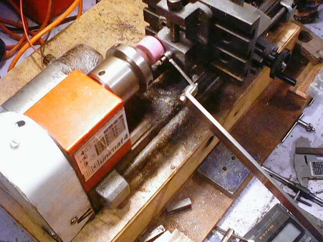
This produced the basic outline shape but not a particularly good finish. To get around this I fitted a grinding wheel into the chuck and repeated the process.
NEW 04/06/2002
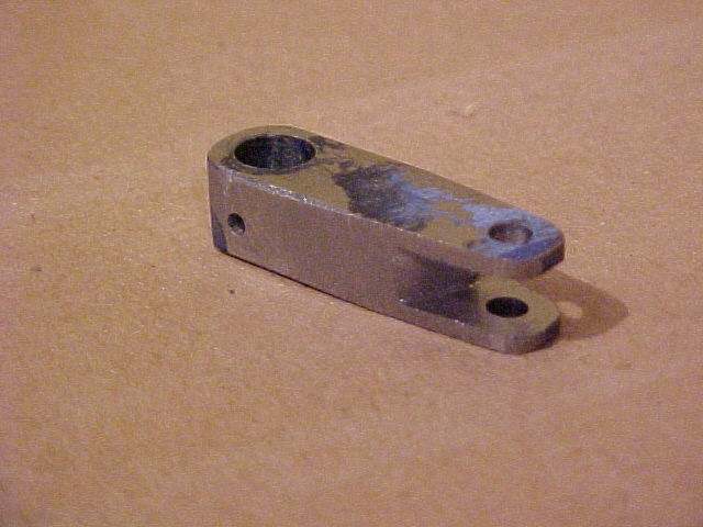
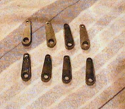
Amazingly the setup worked very well - although things got a bit hairy at times!!!! Here's a picture of the completed arms after profiling and reaming :-
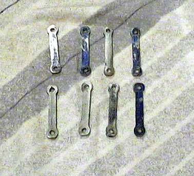
Having completed the lifting arms I turned my attention to the lifting links. These require quite a bit of profiling as they need to be reduced in size along the centre to allow them to swing in the arms. I must admit I haven't got this quite right but I plan to sort this out with a file by fitting each one to suit the arms they will be fitted to.
With these parts done I now needed the pins to allow me to assemble them. I spent a day and a half with a couple of lengths of silver steel bar and emerged with 18 beautiful pins. These are shown in the picture below. The top row are for the lifting arms, the middle row for the reach rod and the bottom row for the brakegear.
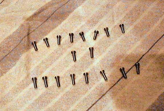
There is one final job left to be done on the pins - they need holes drilling for split pins (1/32"). As there are so many I have made a small jig to help me. This is basically a collar with a hole drilled through it. This is setup in the machine vice and each pin is simply pushed in, drilled and then removed, each pin having an identical hole in - or that's the theory!!
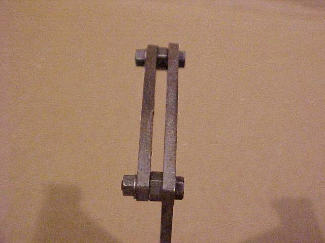
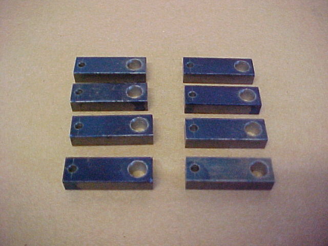
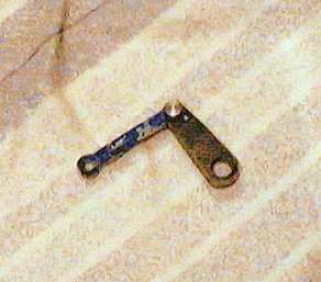
It's now time to start assembling parts. Here's a couple of pictures of the lifting arms / links complete with the pin :-
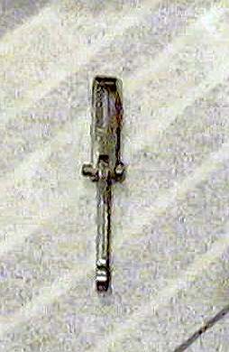
And here's a couple of pic's of the reach rod and reversing arm assembled :-
![]()
![]()