|
|
10
|
Editing Surfaces
|
|
In This Section:
|
|
|
|
|
|
Surface Edit >
Align mesh

|
Aligning Several Surfaces
|
|
|
|
|
Purpose
Align several surfaces with positional or tangent continuity.
Overview
Align mesh is similar to the Align tool, but works on more than two surfaces at a time.
How To
To align surfaces:
-
1
-
Pick the surfaces you want to align.
-
2
-
Click the Align mesh icon, or choose Align mesh from the Surface Edit palette menu.
- If all the surfaces are adjacent, Align mesh aligns them using the settings in the option window.
- If none of the surfaces are adjacent, Align mesh displays an error in the prompt line and does not align.
- If at least two of the surfaces are adjacent, Align mesh asks you whether you want to align the surfaces that are adjacent and ignore the rest.
Tips and Notes
- Surfaces must be adjacent (within the Snap Tolerance) along the entire length of the boundary being aligned.
- The Align mesh tool cannot align surfaces with trimmed sides (such as are created with the N-sided tool).
- Adjust the Snap Tolerance option if you want looser or tighter control over which surfaces are considered adjacent.
- If the average tangent plane at a corner is undefined (impossible to calculate), the Align mesh tool ignores the surfaces and displays an warning in the prompt line.
Options
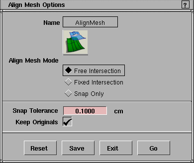
Align Mesh Mode
-
- Free Intersection-enforce positional continuity, then achieve tangent continuity by moving the CVs along the surfaces common boundaries.
-
- Fixed Intersection-enforce positional continuity, then try to achieve tangent continuity by moving the second row of CVs from the surface boundaries on each surface. The surface boundaries remain fixed.
-
- Snap Only-enforce positional continuity only.
Snap Tolerance
-
- The maximum distance allowed between surfaces for them to be considered adjacent.
Keep Originals
-
- On-keep the original surfaces in addition to the new aligned surfaces.
-
- Off-align the surfaces and delete the originals.
See Also
|
Surface Edit >
aAlign hull

|
Aligning Hulls to a Plane
|
|
|
|
|
Purpose
Align surface hulls to their best-fit planes.
Overview
The Align hull tool calculates the best-fit plane for each row of CVs and aligns the CVs to that plane.
Because the tool fits the CVs to an arbitrary best-fit plane, the CVs will usually move only a small distance.
How To
To align the hulls of a surface:
-
1
-
Pick the surface you want to change.
-
2
-
Double-click the Align hull icon, or choose Align hull from the Surface Edit palette menu.
-
The Align Hull Options window appears.
-
3
-
Choose whether to align hulls along the U, V, or both directions, then click Go.
Options
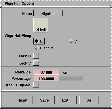
Align Hull Along
-
- U, V, or both U and V.
Lock U
Lock V
-
- Do not move the surface edges in the U or V directions.
Tolerance
-
- The maximum distance to allow between CVs and the alignment plane
Percentage
-
- Move the CVs toward the best fit plane this percentage of the total distance. For example: if a CV must move 5 mm to be aligned, and the Percentage is 0.1, the CV will only move 0.5 mm.
-
- Use this option to align CVs iteratively. If you only want to move the CVs a short distance, use a percentage to move the CVs by small amounts until you reach the level of alignment you want.
-
- When you move the CVs by a percentage, the new CV positions have a new best-fit plane. So moving CVs iteratively by percentages will give a different result than moving them by the complete distance in one jump.
Keep Originals
-
- Turn this option off to delete the original surface after the new, aligned surface is created.
See also
|
Surface Edit >
Create
CurvesOnSurface
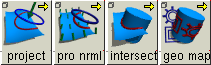
Surface Edit >
Projection Vector
|
Creating Curves-on-Surface from Geometry
|
|
|
|
|
Purpose
Create curves-on-surface from existing curves and surfaces by intersecting surfaces, projecting curves onto surfaces, and mapping curves onto surfaces.
Overview
There are four basic tools for creating curves-on-surface from existing curves:
|
|
|
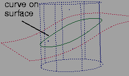
- Intersect. This tool creates curves-on-surface where two surfaces intersect (See page 320).
-
This allows you to trim the surfaces back to the
intersection.
|
|
|
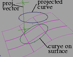
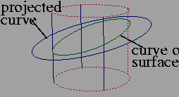
- Project. This tool creates curves-on-surface by projecting a curve along a vector onto surfaces (see page 321).
-
You can change the projection vector with the options or
with the Move project vector and Vector from window tools.
-
This is like shining a flashlight at the curve, and turning
the shadows on the target surfaces into curves-on-surface.
The line between the flashlight, the curve, and the shadow
is the projection vector (see page 321).
|
|
|
- Project normal. This tool is similar to Project, but instead of projecting along a single vector, the curve is projected onto each point on the surface along the normal at that point (see page 322)
-
This tool is very useful for projecting curves that are
parallel to or surround the target surface.
|
|
|
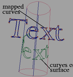
- Geometry mapping. This tool maps world-space curves onto the target surface, similarly to mapping a texture onto a surface during rendering (see page 322).
-
Geometry mapping can produce curves-on-surface that
are impossible with projection or intersection. For
example, you can wrap text curves around a cylinder,
rather than simply projecting them onto the sides.
How To
To create curves-on-surface at the intersection between two surfaces:
-
1
-
Pick the surfaces on which you want to create curves-on-surface (the target surfaces).
|
|

|
-
2
-
Click the Intersect icon, or choose CreateCurvesOnSurface > Intersect from the Surface Edit palette menu.
-
3
-
Click the curve or surface you want to intersect with the picked surfaces. This intersecting surface can be one of the picked surfaces.
-
4
-
If a surface was picked in step 3, the Intersect tool creates curves-on-surface.
- If the Create Curves on Surface option is set to On First Surface, the Intersect tool creates curves-on-surface on the target surfaces, but not on the intersecting surface you clicked in step 3.
- If the Create Curves on Surface option is set to On Both Surfaces, the Intersect tool creates curves-on-surface on both the target and the intersecting surfaces.
-
If a curve was picked in step 3, the Intersect tool adds an
edit point to the curve at the intersection(s).
-
5
-
Repeat step 3 for another intersecting curve or surface if necessary.
To project a curve or surface outline to create a curve-on-surface:
-
1
-
Pick the surfaces on which you want to create curves-on-surface.
|
|
See Active Window under
Project Options below.
|
-
2
-
If the Projection Vector option is set to Active Window, make sure the correct window is active.
|
|

|
-
3
-
Click the Project icon, or choose Create CurvesOnSurface > Project from the Surface Edit palette menu.
-
An indicator appears showing the projection vector.
-
4
-
Click the curve, isoparm, or curve-on-surface you want to project onto the surface(s).
-
The curve is projected onto all picked surfaces along the
projection vector.
-
This operation can take some time depending on the
complexity of the geometry. Press Esc to cancel the
operation.
-
5
-
You can now:
- Continue to click curves to project.
- Select new surfaces and click the Project icon again.
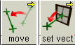
To change the projection vector of the Project tool:
|
|

|
- Click the Move project vector icon, or choose Projection vector > Move project vector from the Surface Edit palette menu.
-
The Projection Vector window opens and a vector
manipulator appears in the view windows.
- Click the handles at either end and drag to move the vector, or type a 3D coordinate to place the handle exactly.
- Type exact values for the handle locations in the Projection Vector window.
|
|

|
- Click the Vector from window icon, or choose Projection vector > Vector from window from the Surface Edit palette menu.
- Click inside a view window to set the project vector perpendicular to that view.
To project a curve along the surface normals to create a curve-on-surface:
-
1
-
Pick the surfaces on which you want to create curves-on-surface.
|
|

|
-
2
-
Click the Project normal icon, or choose Create CurvesOnSurface > Project normal from the Surface Edit palette menu.
-
3
-
Click the curve, isoparm, or curve-on-surface you want to project.
-
The curve is projected onto all picked surfaces along the
surfaces's normals.
-
This operation can take some time depending on the
complexity of the geometry. Press Esc to cancel the
operation.
-
4
-
You can now:
- Continue to click curves to project.
- Select new surfaces and click the Project normal icon again.
To map a curve onto a surface to create a curve-on-surface:
-
1
-
Figure out how you want the curve to map:
- Check the parametric directions of the surface. Use the Reverse direction tool to display and reverse the surface direction if necessary.
- Note which world space axes correspond to the U and V axes of the surface.
-
2
-
Set up the options using the explanations under Geometry mapping Options on page 327.
-
3
-
Pick the surface on which you want to create curves-on-surface.
|
|

|
-
4
-
Click the Geometry mapping icon, or choose Create CurvesOnSurface > Geometry mapping from the Surface Edit palette menu.
-
5
-
Click the curve, isoparm, or curve-on-surface you want to map.
-
The curve is mapped onto the picked surface using the
settings in the Geometry mapping option window.
-
6
-
You can now:
- Continue to click curves to map.
- Select a new surface and click the Geometry mapping tool again.
Tips and Notes
- Surfaces that have curves-on-surface are drawn with a dotted outline.
|
|
See Making a Planar Face from
Bounding Curves on
page 224.
|
- You cannot intersect faces, but you can project and map them onto surfaces.
- If you are using the Active Window option of the Project tool and you are always using the same window, try setting the project vector using the Vector from window tool. That way, you won't have to worry about which window is active.
- To minimize distortion when mapping, the size of the mapped area in world space should be proportional to the size of the surface.
- The Intersect tool can also be used to insert edit points on curves where they intersect a surface or another curve. An edit point is also inserted on the other curve if On Both Surfaces is turned on.
Options
Common Options
Create History
-
- Save the construction history of the new curves-on-surface for later editing. If you turn Create History on, you can modify the curves/surfaces that were used to create the curves-on-surface, and the curves-on-surface will update.
Intersect Options
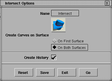
Create Curves on Surface
-
- On First Surface-create curves-on-surface on the picked surfaces, but not on the intersecting surface you clicked.
-
- On Both Surfaces-create curves-on-surface on the picked and the intersecting surfaces.
Project Options
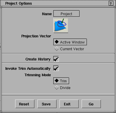
Projection Vector
-
- Active Window-project the curve onto the surface along the view vector of the active window.
-
- Current Vector-project the curve onto the surface along the vector set with the Move project vector or Vector from window tool.
Invoke Trim Automatically
-
- Turn on this option to invoke a Trim tool immediately after the Project operation.
|
|
These options only appear if
Invoke Trim Automatically is
on.
|
Trim/Divide
-
- Choose whether to use the Trim or Trim Divide tool after the project operation.
Project normal Options
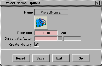
Tolerance
-
- The accuracy of the match between the original curve and the curve-on-surface. The smaller the value, the more accurate the projection, but the longer the calculation time required.
-
- For example, if the Tolerance is 0.01, the curve-on-surface must match the original curve within 0.01 units at each point that Project normal checks.
Curve data factor
-
- Number of times each surface patch is subdivided to get an accurate result.
-
- The default is 1, which is sufficient for most surfaces. Larger values increase calculation time. Only increase the value for very simple surfaces.
Geometry mapping Options
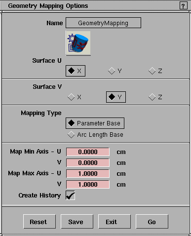
Surface U/V
-
- Set the world space axes (X, Y or Z) that correspond to the U and V directions of the surface.
Mapping Type
-
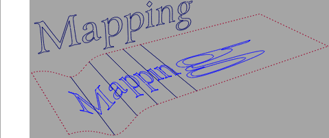
- Parameter Base-proportionally map the defined area of world space to the parameter space of the surface. If the surface has irregular placement of edit points, as in the following example, the mapped geometry will be distorted.
-
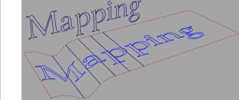
- Arc Length Base-proportionally map the defined area of world space to the arc length of the surface.
Map Min/Max U/V Axis
-
- These values define the area of world space that corresponds to the U and V parameter space of the surface.
-
- For example:
- You are mapping a curve in the XY plane, and you want the curve to fill the mapped surface.
- You are mapping world X to surface U, and world Y to surface V.
- The curve's bounding box is (-4, -2) to (5, 3).
- Enter -4 and 5 as the minimum and maximum U axis values.
- Enter -2 and 3 as the minimum and maximum V axis values.
See Also
|
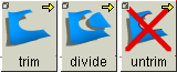
Surface Edit >
Trim >
Trim, Trim divide,
Untrim
|
Trimming Surfaces with Curves-on-Surface
|
|
|
|
|
Purpose
Trim or separate surfaces using existing curves-on-surface.
Overview
Since NURBS surfaces are intrinsically four-sided and do not allow holes, we need a way to visually simulate irregular shapes and holes when using NURBS. The answer is trimming.
Trimming lets you visually cut or divide a surface along a curve-on-surface so it appears to have holes or missing pieces. The trimmed surface, however, is not actually cut. It exists in a hidden form that does not render or affect modeling. You can easily recover the trimmed part of a surface using the Untrim tool.
Creating curves-on-surface and then trimming is a very common way to combine NURBS surfaces in industrial design. The usual process is to design two parts of an object (for example, the body and cover of the CD player in Lesson 9 of the Learning Alias book), then intersect and trim them. This is much easier than trying to create pre-shaped surfaces that fit together perfectly.
You should remember, however, that trimmed surfaces are more complex and can take longer to display and render. For this reason, trimming is not a common technique for creating animated models.
If possible, do not use trimming as your only modeling technique. If there is another (less complex) way to achieve your design goals, you should consider the alternative method first.
Trim History
Similar to construction history, each surface keeps a history of the trims that have been performed on it. The Untrim tool "backs up" one step at a time in the trim history, allowing you to undo a recent trim operation without losing every previous trim. If you want to undo all trims ever performed on a surface, you can set the Untrim tool's Untrim Stages option to All.
How To
To trim a surface:
|
|

|
-
1
-
Click the Trim icon, or choose Trim > Trim from the Surface Edit menu.
-
2
-
Click the surface you want to trim.
-
You can use an already trimmed surface.
|
|

|
-
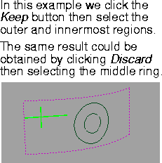
If the surface is valid, a set of three buttons (Keep/Discard/
Go) appears in the lower right corner of the view window.
|
|
|
-
3
-
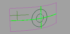
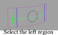
Click the part of the surface (defined by curves-on-surface) you either want to keep or discard.
-
Because the surface is already selected, you do not have to
click a "visible" part of the surface (such as an isoparm or
edge). You can click anywhere on the surface.
-
4
-
The Trim tool places an indicator on the surface where you clicked.
- If you hold down the mouse button when clicking in Step 3, you can move the indicator to a different region on the surface. The cross-hair intersection point determines what region is selected.
|
|
|
- Click the surface again to operate on another region to operate on.
- Click the Keep button to indicate you want to keep the region(s) you clicked, and the rest of the surface should be trimmed.
|
|

|
- Click the Discard button to indicate you want to trim away the region(s) you clicked, and keep the rest of the surface. The indicators turn pink.
-
5
-
Click Go. The region(s) you clicked are kept or discarded.
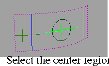
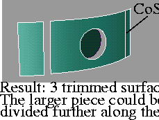
To separate a surface into two or more new surfaces:
|
|

|
-
1
-
Click the Trim divide icon, or choose Trim > Trim divide from the Surface Edit menu.
-
2
-
Click the surface you want to trim.
-
You can use an already trimmed surface.
|
|
|
-
3
-
Click the part of the surface (defined by curves-on-surface) you want to separate.
-
Because the surface is already selected, you do not have to
click a "visible" part of the surface (such as an isoparm or
edge). You can click anywhere on the surface.
-
4
-
The Trim divide tool places an indicator on the surface where you clicked.
|
|
|
- If you hold down the mouse button when clicking in Step 3, you can move the indicator to a different region on the surface. The cross-hair intersection point determines what region is selected.
- Click the surface again to define another region you want to separate.
-
5
-
Click the Go button.
|
|
|
-
The Trim divide tool divides the original surface into as
many new trimmed surfaces as the number of regions you
clicked, plus one: the remaining part of the original
surface.
To untrim surfaces:
-
1
-
Pick the surfaces you want to untrim.
|
|

|
-
2
-
Click the Untrim icon, or choose Surface Edit > Trim > Untrim.
- If the Untrim Stages option is set to Last (the default), the Untrim tool will undo the last trim operation on this surface.
- If the Untrim Stages option is set to All, the Untrim tool will undo all trims on this surface.
- If the surface to untrim has construction history , a confirmation box warns that the history will be removed. Click YES to proceed, or NO to cancel.
>
|
Note:
|
You cannot untrim groups of objects. You must ungroup the
surfaces you want to untrim, or select them directly in the
SBD window, or by using Pick > Component.
|
Tips and Notes
|
|
|
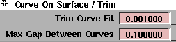
- Tolerances for the Trim tool are in Preferences > Construction options under the Curve On Surface/Trim section.
- Trim Curve Fit allows you to control the accuracy of the trim boundaries created using the trim tool. The default is 0.001 centimeters.
- Max Gap Between Curves is the maximum gap allowed between the endpoints of two curves-on-surface (or a curve-on-surface and a surface edge) to consider them closed when defining a trim region. The default is 0.1 centimeters.
- You cannot use the Align or Attach tools on surfaces created by Trim or Trim divide. Make sure to align or attach surfaces before using a Trim tool.
- Curves-on-surface must be visible to affect trims (toggle with ObjectDisplay > Visible).
- By default, curves-on-surface with a Dashed line style (set with ObjectDisplay > Line Style) are valid for trims.
-
If you want the trim tools to ignore dashed curves-on-
surface, open Preferences > User Options > Alias Preferences.
In the Modeling Options > Trim Options section, turn off Trim
dashed CoS.
Options
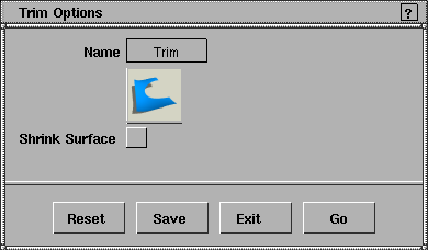
Trim/Trim divide Options
Shrink Surface
-
- Shrink the underlying surface's UV parameters to cover only the visible (non-trimmed) parts of the surface. This option is useful when applying label-style textures to the surface. This option permanently changes the surface and cannot be undone by untrimming.
|
|
|
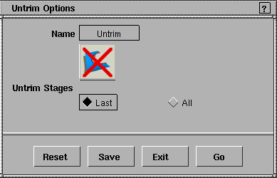
Untrim Options
Untrim Stages
-
- Last-undo the last trim operation on the surface.
-
- All-undo all trims on the surface.
See Also
|