Gate controller
This project is based on Italian manufactered gate system. Originally this system had the PIC MC which died after 5 or 6 years.
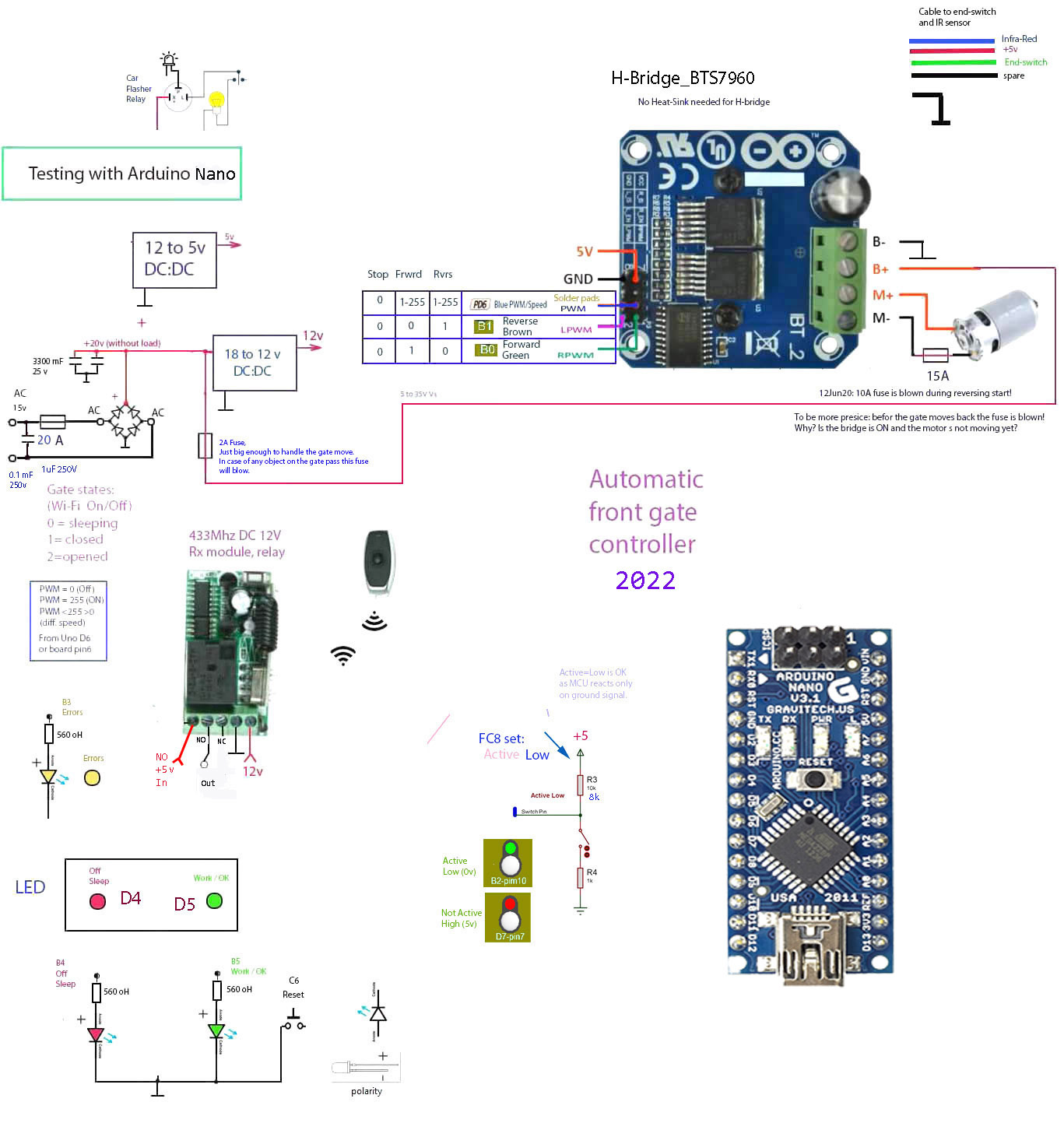
After some time I designed the Arduino-based gate controller (in March 2020).
Operation
Operator opens the gate by using the remote UHF mini-controller (RF 433 mHz).
When the RF Tx button is pressed the relay in the controller Rx module is activated and the (Uno port D2) interrupt pin goes high, waking up the Uno from sleep. The gate state changes from 0 to 1 and gate moves to the open position. The gate slows down before it hits the open end-switch.
Gate states
State0 - sleeping
State1 - gate is closed, starts to open
When the gate state = 1 (the gate is ready to be opened) the Arduino commands H-Bridge -> Motor to open the gate. Gate moves and if the current is not above 2A (fuse in the motor line) it keeps moving.
State2 - gate is opened. Pauses for 50 seconds. Starts to close.
When the fully opened end-switch is activated (= 0v) the motor stops and waits. It moves back to closed position after that.
State3 - Emergency Stop
Ver1 (old). If the obsticle stops the gate the current increases and the current sensor 'tells' Arduino to stop the gate. Gate stops and the system moves into the Emergency Stop state and gate stalls. Operator must manually shut down the system, open the motor key lock and move the gate to closed position. And switch after that the system back on.
Ver2: Only 2A fuse works as an emergency stop device. I tested it by using my hand against the opening gate. Fuse was blown and the gate stopped.
Motor
S-350 Speed 90 motor.
V.12 DC, Max torque - 14 nM.
Speed: 1470 rpm, Made: 15/6/2006
Gate DC motor has the worm gear and can move a heavy metal gate without any problems.
The motor driver is H-Bridge 20A BTS7960.
Power supply
I used some parts from the old PCB for the new design. The transformer is an old as well. Two power modules were added: DC18v to DC12v and DC18v to DC5v.
RF system
Frequency: 433MHz. KR2201 receiving module and button Tx module.
Schematics
The program size was (with LCD) 31 Kb at first but after some simplification it is apprx 7kB now.
Note
Would be interesting to discuss this design with somebody, who did the same project.
Articles, Links
How to choose the correct sliding gate operator?
Google search for gate opener
Note 2
The current sensor -> not is use anymore.
Note 3
The end-switches should be sealed from the weather very well if you want to have a good operation of your system.
Note 4
The end-switches state is Active Low to eliminate the false trigger signal for MCU.
Update: 2-Jan-2022
A new code: apprx 7 kB.
New Hex file