Nano as the sine wave generator
Credits to:
https://yopiediy.xyz/wp-content/uploads/2022/11/ArduinoUnoSPWM.zip
and Syed Tahmid Mahbug.
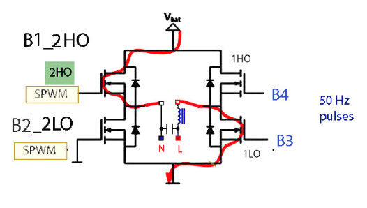
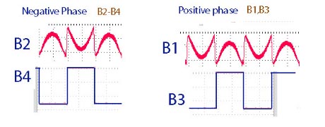
The H-Bridge has 4 mosfets. If we supply the SPWM to left side of this bridge (2HO, 2LO) and the 50 hz pulses to the right side of the bridge, we can force the h-bridge to be open (by using B4 input or B3) and let the SPWM (only half of the sine-wave) to pass to the load.
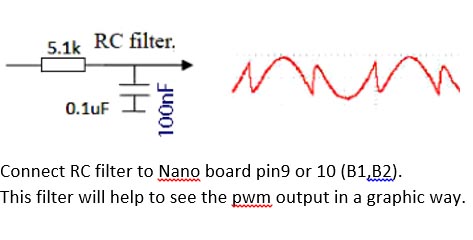
Note: LC filter is used to simplify the test of Nano outputs.
-----------------------------
If you go to the above link (Yopie DIY) you can find all the information you need.
If you want to study the work of Arduino Atmega328 Timer1, it will help even more.
Timer1 has two registers
TCCR1A ,TCCR1B
Both registers has MSB and LSB values set.
TCCR1A register MSB controls the way Timer1 counter named TCNT1 controls pins B1,B2 state.
If TCNT1 counts up (0->400),
If OCR1A register value = TCNT1 value, pinB1 state at the moment of both values equal = 0.
If OCR1B register value = TCNT1 value, pinB2 state at the moment of both values equal = 1.
If TCNT1 counts down (400->0),
If OCR1A register value = TCNT1 value, pinB1 state at the moment of both values equal = 1.
If OCR1B register value = TCNT1 value, pinB2 state at the moment of both values equal = 0.
At the code: If OCR1A = FCL_VAL value (this value is taken from the LUT table), B1,B2 toggles,the pulse width is changed.
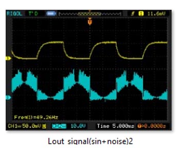
The blue signal is the one I have with the bad LC filter.
However you can see a sine-wave.