No one yet had succeeded in keeping a large number of mechanical clocks
in absolute step. The rapid growth of the railways during the middle of the
last century gave the stimulus to find means of ensuring that clocks did in
fact indicate the same time.
R L Jones
A pioneer in synchronizing clocks was R L Jones, stationmaster of Chester.
In his patent no.702 of 1857 Jones adopted Bain's system of sympathetic pendulums.
A mechanical master clock provided the electric pulses to keep the pendulums
of his ordinary key-wound clocks in step. The bob of these key-wound clocks
consisted of a coil sliding over two permanent magnets. The electric pulses
received from the master clock kept these secondary clocks in harmony with
his master clock. He used the tower clock of Chester as master clock providing
the electric pulses to control his secondary clocks.
4.
Synchronization
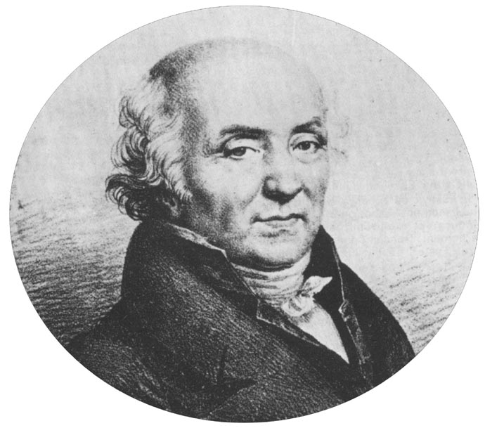
Abraham
Louis Breguet (1747-1823) As early as 1793
Breguet devised a system to synchronize watches.
On placing a watch
on his fully mechanical master clock, "La Pendule Sympathique",
it not only winds the watch, sets its hands to the hour but also adjusts its
rate of time. A remarkable achievement. Brequet neither wrote nor published
any account of his work and his invention was probably unknown to anyone beyond
his immediate circle.
In the watch is a
separate train wound independently. The synchronization signal from the master
clock lets the setting-train off doing what it has to do. I do not know how
things work in detail.
James
Ritchie
In 1872 James Ritchie, a clockmaker from Edinburgh,
also improved Bain's system of sympathetic pendulums (patent no.2078). On
the right-hand side we see the pendulum of a secondary clock fitted with a
coil passing over two permanent magnets. On the left-hand side is the pendulum
of the mechanical master clock. By means of contacts, fitted to the pendulum
of the master clock, the coil of the secondary pendulum is energized at each
swing keeping it in absolute step with the master clock.
A reverse gravity escapement, connected to the pendulum of the secondary
clock, drives the hands of its dial.-------------------animation
In 1878 Ritchie also devised a system of synchronization (patent no.333) relying
on the use of a self-propelled secondary clock having a slight gaining rate.
A synchronizing current of 15 seconds duration, terminating exactly at the
hour is received by the electro-magnet of the secondary clock. Its electro-magnet
will pull down an armature holding-up the clock. However, the armature cannot
move until the minute hand gets to the hour and the notch in a cam is able
to receive the end of the armature. A pin fitted to the other end of the armature
then holds-up the clock until the cessation of the current when the armature
falls away.
John
Alexander Lund
In 1876 Lund took out patent no.3924 for a forcible correction of the minute
hand of secondary clocks.
Left dial: levers force the minute hand to the hour. Right dial: a V-shaped cam slides upwards forcing the minute hand to the
hour by means of a pin fixed to the back of the minute hand.
We have seen some systems in which the hands of secondary clocks are
synchronized by a master clock. There were also systems devised that corrected
the rate of time of the pendulum.
John
Matthias Augustus Stroh (1828-1914) In 1869 Augustus
Stroh, a watchmaker from Furtwangen, Germany, who came to England in 1851and
worked for Wheatstone, devised a system that synchronized the rate of time
of a pendulum. Stroh would later become well know for his inventions related
to musical instruments.
In his patent no.3028 a beam carries on the right a small subsidiary pendulum,
counter-balanced by a weight on the left. The suspension spring of the little
pendulum passes between fixed jaws and its bob is linked to the pendulum of
the clock to be synchronized. A synchronizing signal pulls a feeler connected
to the rocking beam over the point of a cam, mounted on the minute wheel of
the clock, and so the feeler is pushed up or down dictated by the position
of the cam. As a result, the beam is rocked and so the effective length of
the subsidiary pendulum is altered.
The use of a
short subsidiary pendulum linked to the main pendulum is only a convenient
way of diluting the synchronizing effect.
Robert
James Rudd (1844-1932)
Another synchronizer that corrects the rate of time of the pendulum (patent
no.19337) was invented by Rudd in 1898.
On receiving the synchronizing signal, .
the electro-magnet attracts its armature turning a Z-shaped lever. By means
of a C-shaped spring a lever is now reset into whatever position may be dictated
by a snail fitted to the seconds hand. The Z-shaped lever also releases another
lever provided with pins embracing the suspension spring of a subsidiary pendulum.
When this lever is raised or lowered it will alter the effective length of
the subsidiary pendulum and so influence the rate of time of the pendulum.