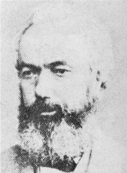
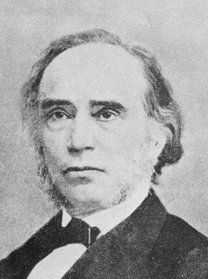
Carl
August Steinheil (1801-1870)
In 1839 Carl August Steinheil, professor at Munich university,
built a mechanical clock fitted with a rocking contact under its pendulum.
His
master clock was placed in the Educational Institute of Munich and sent-out
electric pulses to a secondary clock placed at the
Observatory of Bogenhausen at a distance of some 2 kilometers.
His secondary clock was fitted with a permanent magnet and a solenoid. The
solenoid moved the magnet fixed to an anchor escapement driving the hands
of the secondary clock.-- --- --animation
As
the pendulum swings, it tips-over a rocking bar allowing pins attached to
it to make contact with mercury held in glass tubes under the bar. In this
way contact is made at each swing of the pendulum, reversing the direction
of the current and giving the secondary clock its electric pulse.
For the first time, using one clock, the same time was indicated
at different locations, way apart from each other.
Steinheil also suggested creating large loops of electrical
wires to distribute uniform time in large cities; half minute or one
minute signals would be sufficient. He furthermore suggested using
electromagnetic currents, generated by a magnet attached to a pendulum
swinging in and out of a fixed coil, to drive small secondary clocks and mentioned
the idea of using one master clock to synchronize other pendulums of various
lengths every 2 minutes.
Steinheil was the very first to apply electricity to horology and transmit
time signals.
However,
Alexander Bain,
a
clockmaker from
Edinburgh,
was to form the key
stone of electrical horology. Alexander Bain (1810-1877) In
1840 Alexander Bain, who had come to London in 1837, took some models of an
electric clock to Charles Wheatstone, professor of physics at King's College.
Alas for Bain he could not have gone to a worse man. Wheatstone gave Bain
£5 with a promise of more and advised him to postpone any further work and
not to tell anyone. In November 1840 Wheatstone exhibited a model, supposedly
of his own design, to the Royal Society of London.
However,
the previous month in October 1840, Alexander
Bain and his partner at that time, chronometer
maker John Barwise, had applied for the first electric clock patent in England.
Bain's patent was granted in 1841 and Wheatstone was forced to withdraw his
model. This started a life-long quarrel between Bain and Wheatstone.
In his patent no.8783 of 1841 Bain anticipated most applications of electricity
to horology, such as:
- the use of electro-magnets to store energy in a weight or spring
- the use of electro-magnets to drive secondary clocks - the pendulum to
operate contacts to wind-up other clocks - the use of a master clock to regulate the pendulums
of other clocks - the use of a master clock to synchronize other clocks..
At the end of his patent Bain envisaged uniform distribution of time throughout
the country. In this illustration we see Bain's first conception
of an electric clock system. The
pendulum is of seconds beat driven by a key-wound movement. A little bracket
rubs backwards and forwards along the surface of some insulating material
bisected by a metal strip. So, contact is made every second and the electric
pulses are transmitted to the secondary clock. ----------
--------animation
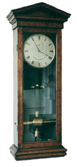
Not until 1843 (patent no.9745) and 1845 (patent no.10838) did Bain
construct electro-mechanically driven clocks. However, these clocks still
contained many teasing troubles such as the poor contact making and their
dependency on the condition of the battery.
The picture shown here is such a clock but of a much later date.
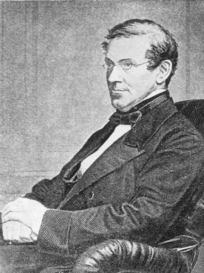
Charles
Wheatstone (1802-1875)
Charles Wheatstone, inventor of the Wheatstone bridge, was professor of physics when Bain
came to him for advice on his electric clock. The
model shown to the Royal Society in November 1840 consisted of an ordinary key-wound
movement.
Mounted along with its escape wheel was a brass wheel with sixty slots cut
in its periphery and filled with wooden segments. A spring would make contact
every second and so impulse the electric dial movement.
The system used is a primeval commutator destined in a later age for the
dynamo and the motor but rather impossible for a clock due to its friction.
At the same time Wheatstone exhibited this model, he also described another
clock in which Faraday's magneto-electric currents are used. This clock will
be described later.
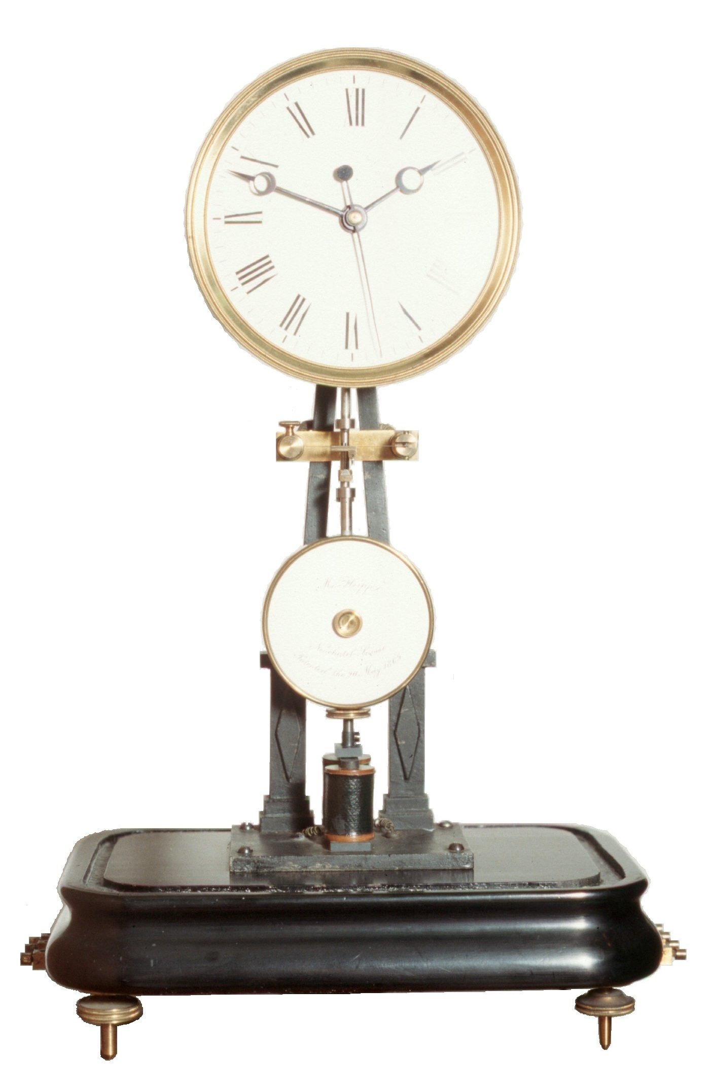
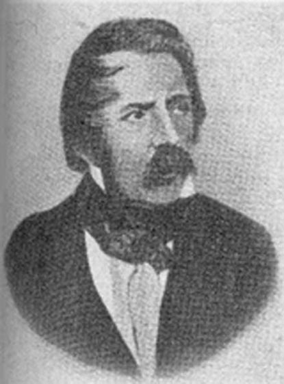
Matthäus Hipp (1815-1893)
Around 1842 Matthäus Hipp of Reutlingen, Germany,
invented the famous Hipp toggle or butterfly escapement,
but it wasnt until 1869 that
he applied for a patent. In 1849 his application for director of the
Clockmakers School at Furtwangen was turned down for political reasons. So, in
1852 Hipp decided to leave Germany and join the Swiss Telegraph Administration
to become a director shortly after. Beside his function at this state-owned
company he continued working on high precision clocks. As a result of his
success as a clockmaker and inventor he started his own business in Neuchâtel in 1860. His clocks were a big success
and due to their great reliability his system of electric clocks was installed in
many Continental cities.I.........................
In his early clocks the toggle is suspended under the armature placed just
below the bob. The toggle is allowed to trail backwards and forwards o
ver a notch mounted on the upper spring of a pair of contact springs.
As a result of the gradually decreasing arc of the pendulum
the toggle will eventually engage the notch fixed to the top spring and force
this spring into contact with the lower spring and so energize the electro-magnet.
The electro-magnet is placed a little off center and
when energized will increase the arc of the pendulum by attracting the armature.
In later models the toggle is suspended from the contact spring and the notch
attached to the pendulum. The contact spring is now placed well above the
pendulum bob. -----animation
A lever is lifted by the pendulum as it swings to the left and when the
pendulum returns to the rigth a pawl will turn the count wheel tooth by tooth.
The hands of the dial are moved by the count-wheel.
Although the energy required to make contact is taken from the pendulum,
this is only done occasionally at wide intervals of time. The electro-magnet
is energized when the pendulum is passing through its zero position
when its kinetic energy is at its maximum and the interference to the freedom
of the pendulum is practically negligible.
Hipp was the first to employ a count wheel to horology.
 His
master clock was placed in the Educational Institute of Munich and sent-out
electric pulses to a secondary clock placed at the
Observatory of Bogenhausen at a distance of some 2 kilometers.
His
master clock was placed in the Educational Institute of Munich and sent-out
electric pulses to a secondary clock placed at the
Observatory of Bogenhausen at a distance of some 2 kilometers.