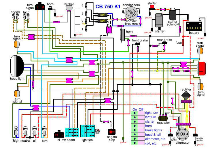
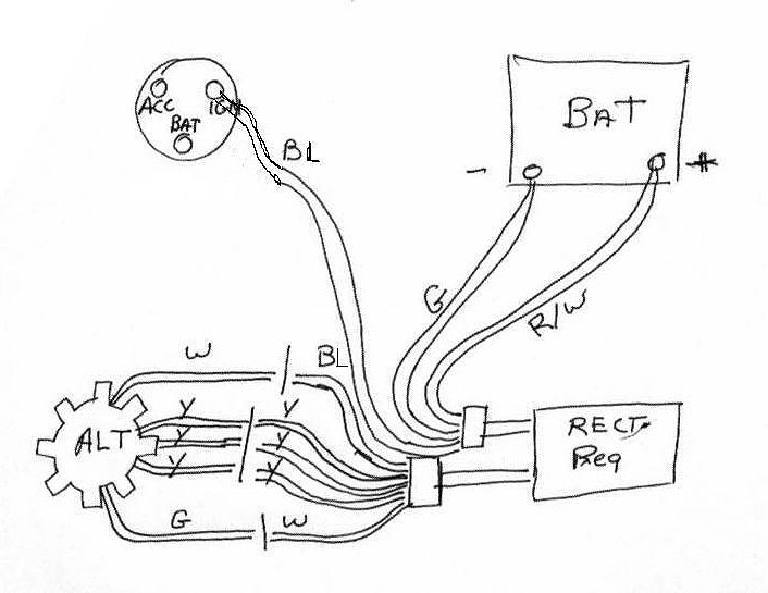
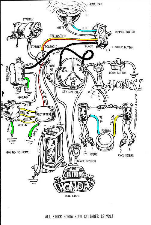
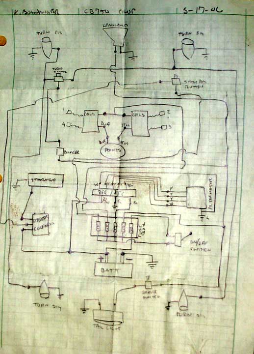
To start off the electrical on this chop, I did some research on Hondachopper.com and came up with the three schematics located to the right. I basically took that info and put together my own wiring diagram that incorporated everything I had on my bike.
This electrical system will be utilizing a combined Regulator/Rectifier unit form an '83 DOHC 750. This will neatly replace the stock system.
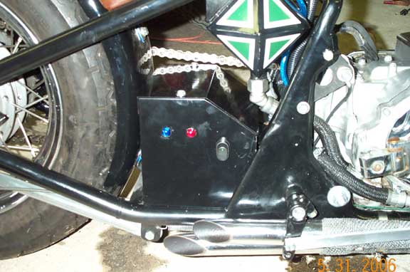
The heart of this electrical system is the battery/electrical box. I detailed the build of this box in an earlier section. It can also be seen mounted on the bike in the picture below. The following components are located in or on this box: battery, fuse bank, regulator/rectifier, starter solinoid, blinker relay, idiot lights and the on/off switch.
Most everything was wired using 16 ga stranded wire. 10 ga and 12 ga were used in other high load applications (starter, main ground, main power). All of the connections were solidered with shrink tubing covering the joint.
I utilized a simple 30 amp toggle switch in place of the typical key switch (most bikes are stolen using a truck not driven off ayway). The two idiot lights you see are for oil pressure (red) and neutral (blue). Wiring was required for all of the typical systems on a motorcycle: blinkers, tail light, head light, charging system, ignition system (points, coils) and starter.
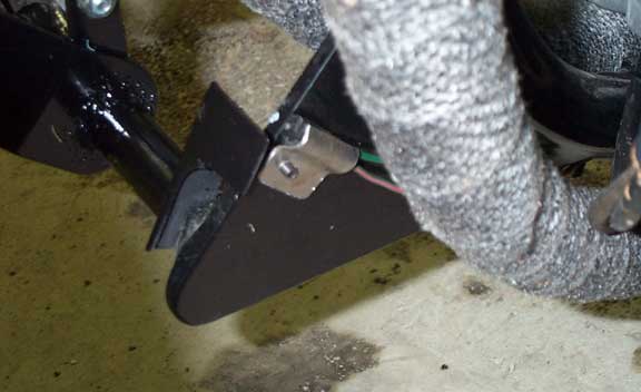
For the break light a switch has to be used to indicate when the brake is being applied. I utilized the stock (I think) brake switch and triggered it off the forward controls.
I tried to neatly hide all of the wiring to the best of my ability. When I couldn't go thru the frame I used split lume to hide the wiring.
|