|
Solid Texture Types
|
|
|
|
|
There are several different types of solid textures.
Projection Texture
The Projection texture converts a two-dimensional texture or image file into a three-dimensional texture by projecting it in one or several directions. See Projection Texture on page 191.
|
|

|
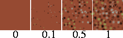
Snow Texture
The Snow texture simulates snow that has fallen on a surface. See Snow Texture on page 204.
|
|

|
sCloud Texture
The sCloud texture simulates clouds, but can also be used to create steam, smoke, or fire effects. See sCloud Texture on page 206.
|
|

|
sFractal Texture
The sFractal texture represents a three dimensional random function with a particular frequency distribution (a fractal). See sFractal Texture on page 210.
|
|

|
sMarble Texture
The sMarble texture simulates marble: a vein material sandwiched between layers of filler material, where the vein material diffuses into the filler material. See sMarble Texture on page 211.
|
|

|
sRock Texture
The sRock texture simulates rock using a random, three dimensional distribution of two different types of grain material. See sRock Texture on page 213.
|
|

|
Leather Texture
The Leather texture simulates leather, but can also be used to simulate other materials, including alligator skin, Styrofoam, and concrete. See Leather Texture on page 214.
|
|

|
Granite Texture
The Granite texture simulates granite using a random, three dimensional array of three different types of spheres suspended in a medium. See Granite Texture on page 217.
|
|

|
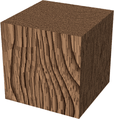
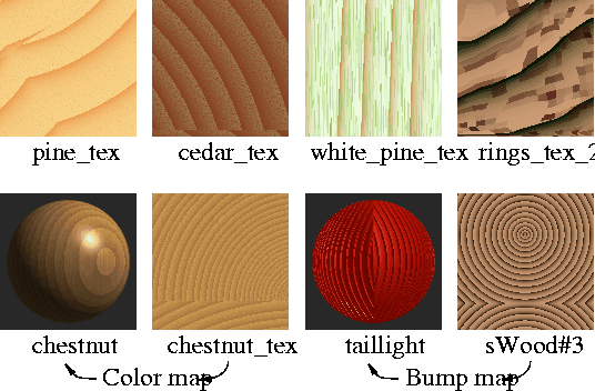
sWood Texture
The sWood texture simulates wood by projecting a two dimensional wood pattern. See sWood Texture on page 219.
Volume Texture
The Volume texture allows the Ball texture to use multiple image files. See Volume Texture on page 222.
Projection Texture
|
|
|
|
|
This feature is available in Alias PowerAnimator, Studio, and AutoStudio, and is a purchasable ConceptModeling option. |
|
|
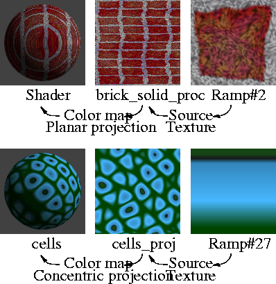
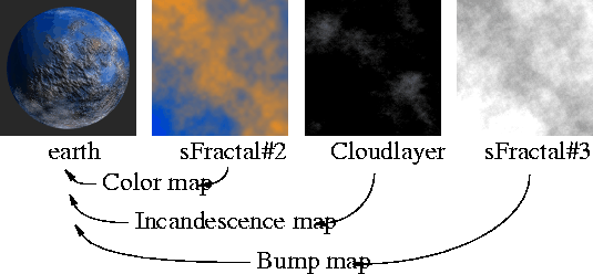
The Projection texture converts a two-dimensional texture or image file into a three-dimensional texture by projecting it in one or several directions. This is the same method used by the sMarble and sWood textures, so you can, for example, use scanned or painted image files with the Projection texture to create a variety of three-dimensional wood or marble textures. The Projection texture is also useful for converting a surface texture or image file to a solid texture to avoid texture distortion due to non-uniform surface parameterization.
Note the following when using the Projection texture:
- When using the Projection texture with textures that use fractal noise (for example, Fractal, sFractal, sCloud, sMarble), keep the Recursion Depth Level_min and Level_max values as low as possible to minimize rendering time. See Recursion Depth on page 186.
- You can use the Surface Placement and Label Mapping parameters of a texture that is mapped to a Projection texture to adjust the projection effect.
- You can create a Projection Object before creating the actual texture in the Multi-lister, by using the Texture Projection Object tools.
Projection Texture Parameters

|
|

|
Projection
-
- The projection method used to create a three-dimensional texture from a two-dimensional texture.
| PLANAR
| Extrudes the texture along the Z axis of the texture transformation.
|
| SPHERICAL
| Wraps the texture 360 degrees around the Y axis to form a sphere centered at 0,0,0. There are two pinch points at the
-Y and +Y poles.
|
| CYLINDRICAL
| Wraps the texture 360 degrees around the Y axis to form a cylinder located between -1 and 1 on the Y-axis. There are two pinch points at the -Y and +Y poles.
|
| BALL
| Wraps the texture 360 degrees around the Z axis like a wrapper around a lollipop. There is one pinch point at the
-Z pole.
|
| CUBIC
| Creates six copies of the texture, and projects them from 0,0,0 in six directions. The projection in each direction resembles a pyramid. The overall projection resembles a cube with a copy of the texture on each face. There are no pinch points, so CUBIC can be used to map repeating textures onto a sphere.
|
| TRIPLANAR
| Extrudes the texture along either the X, Y, or Z axis (the axis closest to the normal at that point on the surface).
|
| CONCENTRIC
| Projects a random vertical slice of the texture from the center to the outside edge of each voxel. A voxel is a volume element (a cube). A certain amount of 3D space will contain several voxels. The size of individual voxels is based on the size of the Texture Placement Object. A surface that has a CONCENTRIC Projection texture mapped to it will appear to be carved out of a three-dimensional array of cubes, where the color of each cube in the array varies from the cube's center to its edge. For example, try using a Ramp as the Source Texture, and scale the Texture Placement Object very small.

|
| CAMERA
| Extrudes an image plane along the camera's (or the current window's) view line. To use this setting, see below.
|
-
- The projection types described above represent the defaults. You can customize the projection effect by transforming the Texture Placement Object (for example, non-proportional scaling or rotating), or by varying the Noise Parameters or the Solid Noise Frequencies parameters.
To use the CAMERA projection method:
-
1
-
Set Projection to CAMERA. The Projection Texture Parameters window expands, listing all cameras that have an image plane. (You can only use the CAMERA projection method for cameras that have an image plane.)

-
2
-
Click the Projective Camera toggle box for the camera you want to create a Projection texture for.
-
3
-
Click the Create button. A Stencil texture representing the image plane is automatically mapped to Source Texture.
Source Texture
-
- The two-dimensional texture or image file projected to create a three-dimensional texture.
-
- If you map Source Texture with a File texture, make sure that the File texture's Filter parameter is set to either NONE or BLEND. Higher order filters (QUADRATIC, QUARTIC, and GAUSSIAN) give unpredictable projections.
-
- Although you can use an environment texture or solid texture as a Source Texture, the results will be unpredictable.
Noise Parameters
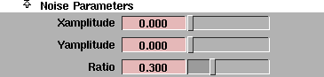
The Projection texture creates a three dimensional texture by projecting a two dimensional texture. The Noise Parameters control the randomization (using fractal noise) of the texture in the direction the texture is projected.
Xamplitude, Yamplitude
-
- A scaling factor applied to all values in the fractal noise about the average value, in the texture's X and Y directions. The Projection texture will render faster if the Xamplitude and Yamplitude values are both 0.
-
- The valid range is 0 to ·. The slider range is 0 (no noise) to 1 (strong noise). The default value is 0.
Ratio
-
- Controls the frequency of the fractal noise. The valid/slider range is 0 (low frequency) to 1 (high frequency). The default value is 0.3.
Solid Noise Frequencies
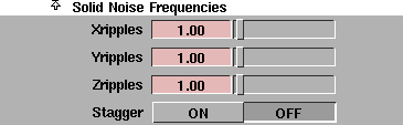
Xripples, Yripples, Zripples
-
- Determines how wavy the texture is in the X, Y, and Z directions. These parameters represent the scale of the fundamental frequency of the fractal used to generate the texture. The valid range is 0 to ·. The slider range is 0 to 20. The default value is 1.
Stagger
-
- Offsets repeated patterns of the texture (when the two-dimensional texture's Urepeat value and/or Vrepeat value is greater than 1) so that alternate rows are offset exactly half, like bricks in a brick wall. When Stagger is OFF, the repeated patterns line up horizontally and vertically. The default setting is OFF.
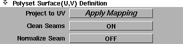
Polyset Surface (U,V) Definition
|
|
|
The Polyset Surface (U,V) Definition parameters have no effect on the Projection texture itself. Instead, you use them to re-parameterize a polyset so that a surface texture mapped to the polyset will resemble a Projection texture.
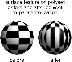
If you animate a polyset that uses a Projection texture, the polyset will appear to flow through the texture. You can solve this problem by re-parameterizing the polyset and then replacing the Projection texture with a surface texture. You may also need to re-parameterize a polyset that originated in another application and was imported with inadequate texture coordinate information (for example, a DXF file).
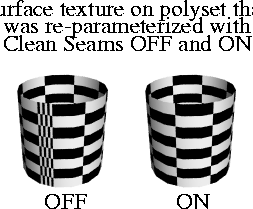
When you map a surface with a Projection texture that uses a cylindrical, spherical, or ball projection type, the texture will have a seam or pole. A seam exists when the texture wraps around a surface and its two opposite edges touch (where the surface's UV parameters jump from 1 to 0). A pole exists when the texture becomes pinched together (where the surface's UV parameters become crowded together).
|
|
|
If you re-parameterize a polyset using a Projection texture that uses a cylindrical, spherical, or ball projection type, and then map a surface texture to the polyset, the texture may appear distorted at the seam or pole. For example, the entire texture may be repeated along the seam. To remove this distortion, set Clean Seams ON before you re-parameterize the polyset. When Clean Seams is ON, however, UV parameters may no longer be within the 0 to 1 range. This is not a problem for polysets within Alias, but it may be a problem for other applications to which you intend to export your data. To scale UV parameter values back to within the 0 to 1 range, set Normalize Seams ON before you re-parameterize the polyset.
You can also re-parameterize a polyset using the Apply UVs tool (see Mapping Vertices to Projections and NURBS Surfaces on page 110 of the Polygonal Modeling in Alias book).
To re-parameterize a polyset:
-
1
-
Pick the polyset(s) you want to re-parameterize.
-
2
-
Create a new shader and click the Map button beside any parameter in the shader's Control Window. (The specific parameter you map the Projection texture to is unimportant.)
-
3
-
Select the Projection texture from the Texture Procedures window.
-
4
-
Select a Projection type in the Projection texture's Control Window.
-
5
-
Position and orient the Projection texture's Texture Projection Object in the modeling windows.
-
6
-
In the Projection texture's Control Window, set Clean Seams and Normalize Seams ON, and click the Apply Mapping button beside Project to UV. The polyset is now re-parameterized.
-
7
-
Create a new shader (or use an existing shader) that uses a surface texture only (no environment textures or solid textures), and assign it to the polyset. The surface texture will now appear as if it were projected onto the polyset.
-
If, after rendering, you are not satisfied with the position
and orientation of the texture on the polyset, you can re-
parameterize the polyset by re-positioning and re-
orienting the Projection texture's Texture Projection Object,
and then clicking the Apply Mapping button again.
Project to UV - Apply Mapping
-
- Re-parameterizes the selected polysets by mapping the vertices of the polygons to the Projection texture. A surface texture mapped to the re-parameterized polyset will resemble a Projection texture.
Clean Seams
-
- Removes texture distortion at seams and poles when a polyset is re-parameterized using a Projection texture that uses a cylindrical, spherical, or ball projection type. If Cleans Seams is ON, UV parameters may no longer be within the 0 to 1 range. The default setting is ON.
Normalize Seams
-
- Scales UV parameters to within the 0 to 1 range when a polyset is re-parameterized. The default setting is OFF.
Effects
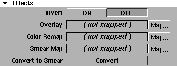
The Projection texture has an additional Effects parameter: Convert to Smear. See Effects on page 103 for a description of the other Effects parameters.
Convert to Smear
-
- Replaces the Projection texture with the Source Texture, and applies a Smear Map so that the texture has the same visual effect on the surface as the original Projection texture.
-
- Often times a texture is best applied to a surface using a 3D projection, however this can create problems when the surface is morphing. The convert to smear feature allows surfaces to be reparameterized to match a projection by using a smear map. This freezes the texture onto the surface. The effect is similar to convert solid texture, but allows for more freedom after the convert is done, and does not degrade texture resolution. One can get away with much lower resolution maps (smear maps) and animated textures are easily handled. Convert solid texture may still be preferred for some cases, however, particularly when the texture may be touched up in 3D paint.
To use Convert to Smear:
-
1
-
Select the surfaces you want to create a smear map for.
-
2
-
In the Multi-lister, double-click the Projection texture to open its Control Window.
-
3
-
In the Projection texture Control Window, click the Convert to Smear button. A dialog box appears.
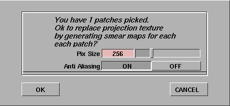
-
The default Pix Size is 256 pixels square. Image files are
created and sized so that the Pix Size corresponds to the
longest dimension of the largest selected surface. If more
than one surface is selected, the other image files are
proportionally smaller. The valid range is 8 to 1024 pixels.
|
Tip:
|
Larger image files require more memory to render, and
depending on the render specifications may not noticeably
improve render quality. Anti Aliasing is recommended in
most circumstances, but Convert to Smear will take four
times longer than if Anti Aliasing is OFF.
|
|
Note:
|
Convert Solid Tex places the newly generated image files in
a sub-directory (that has the same name as the shader being
converted) in the pix directory of the current project.
|
-
4
-
Click OK. Information is displayed in the information line.

-
The progress bar at the far right indicates the status of the
current pix creation.
-
5
-
When the Convert to Smear operation is complete:
- the Projection texture is replaced by its Source Texture,
- a File texture is mapped to this texture's Smear Map parameter, and
- the File texture's Per Object Images list contains a separate image file for each selected surface.
-
Each selected surface now has its own Smear Map which
has all of the same properties as the original Projection
texture.
Notes
- Because the Convert to Smear operation destroys the Projection texture, you may want to save this texture (or copy the shader it is mapped to) before using Convert to Smear.
- If you press Esc during the Convert to Smear operation, the files created up to that point will be correct, but will not necessarily be assigned. Also note that even if you delete the shader used by Convert to Smear, the image files will still exist in a directory with the same name as the original shader in the current pix directory. If you perform a second Convert to Smear operation using the same shader and objects, the previously created files will be overwritten without warning.
- You can use Convert to Smear for both spline type surfaces and polysets or faces.
- Any image files created are referenced on the Per Object Images list of the new file texture. Each surface gets its own image file for every Projection texture converted. The File texture created has no default Image file, only per object files, therefore the shader swatch does not display the file texture.
-
To display the texture on the shader swatch, copy any
image file name from the Per Object Images list to the
default Image field (click in the Object list to highlight the
image file name, then click in the default Image field with
the middle mouse button to paste).
Convert to Smear has the following limitations:
- If Wrap is OFF for the Projection texture, Convert to Smear will not convert the texture properly.
- The Source Texture can only have certain Surface Placement and Label Mapping settings:
- Uoffset, Voffset, Utranslate, and Vtranslate can be set to anything
- Rotate should be set to 0
- Ucoverage and Vcoverage should be set to 1
- Urepeat and Vrepeat must have the same value; the Rgbmult on the Smear Map must be scaled by the repeat value. For example, if Urepeat and Vrepeat are both 5, then set the Rgbmult "value" on the Smear Map to 5.
- If the Source Texture has an image file or texture mapped to Rgboffset, Rgbmult, or Overlay, then you must map a copy of the Smear Map (the File texture created by Convert to Smear) to that image file or texture.
- Bump and displacement maps may show artifacts.
Projection Tools
There are two ways to create a Projection texture: using the Multi-lister or using the Projection tools. To create a Projection texture in the Multi-lister, you first create a shader, map a Projection texture to the shader, and then position the Projection texture using the corresponding Texture Projection Object. The Projection tools let you create a Texture Projection Object in the modeling window first, and then they automatically create the corresponding shader and Projection texture in the Multi-lister.
There are eight different types of Projection tools, representing the eight different types of projections. See Projection on page 192 for a description of each projection type.
Projection Options
Each Projection tool has a similar option box.
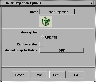
Make global
-
- Makes all projection tools default to the options you last saved (using the Save button).
Display editor
-
- Automatically opens the Projection texture's Control Window after you place the Texture Projection Object in the modeling window.
|
|

|
Magnet snap to B-box (Magnet snap to Bounding-box)
-
- Snaps the Texture Projection Object as you move it in the modeling windows as listed below.
| SELECTION LIST
| snaps to selected components (for example, CVs or edit points)
|
| FROM SELECTED DAGS
| snaps to selected objects
|
| OBJECT
| snaps to objects
|
| OFF
| does not snap to anything (default)
|
-
- If Magnet snap to B-box is set to SELECTION LIST, FROM SELECTED DAGS, or OBJECT, the Draw snap box and Uniform scale options become available.
-
- The Magnet snap to B-box option is not available for the Camera Projection tool.
Draw snap box
-
- Displays the XYZ bounding box of the object being snapped to. This option is not available for the Camera Projection tool.
Uniform scale
-
- Makes the projection object square. If Uniform Scale is off, then the projection object is non-proportionally scaled to the shape of the bounding box of the object being snapped to. This option is not available for the Camera Projection tool.
Snap to camera
-
- Matches the position and orientation of the Texture Projection Object to the modeling window's camera. This option is only available for the Camera Projection tool.
To use the Projection tools:
-
1
-
Select a tool from the Objects cascading menu, or click one of these icons:

|
|
The Texture Projection
Object is different for each
Projection type.
|
-
2
-
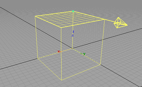
Click or click-drag in a modeling window to place the pivot point of the new Texture Projection Object.
-
A new shader appears in the Multi-lister, having a Projection
texture mapped to its Color.

Tips
- The projection objects are moved by their pivot points. The Planar and Tri-planar projections are not centered on their pivot points when they are created.
- When using the Camera projection, it may be helpful to pick the objects you want to texture first, then use the Look at tool in the Cameras palette before creating the projection object.
Snow Texture
|
|
|
|
| |
|
|
The Snow texture simulates snow that has fallen on a surface.
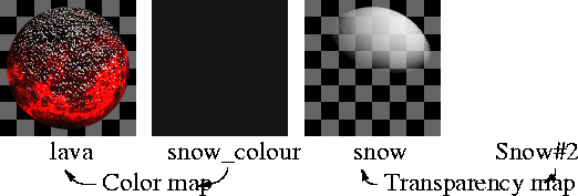
To make snow appear on all objects in your scene, apply the Snow texture as a transparency map on a white shader, and then layer this shader onto other shaders. This way, the snow can have its own unique shading attributes.
Try combining a Fractal bump map with a Snow color map. The snow will only appear on the peaks and valleys of the bump mapped surface. For best results, set the Fractal bump map's Amult and Blurmult values to a low number.
To simulate windswept snow, rotate the Snow texture by rotating the 3D Placement Object about a horizontal line.
Snow Texture Parameters
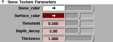
Snow_color
-
- The color of the snow that lies on the top of the surface.
Surface_color
-
- The color of the surface that the snow lies on top of.
|
|
|
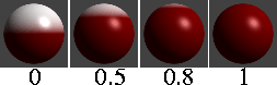
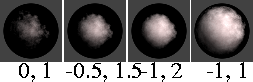
Threshold
-
- Determines the maximum slope that will hold snow. The valid/slider range is 0 (90 degrees from horizontal) to 1 (0 degrees from horizontal). The default value is 0.5 (45 degrees from horizontal).
|
|
|
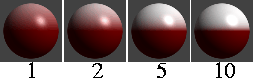
Depth_decay
-
- The rate at which the snow color blends into the surface color. The slider range is 0 to 10. The default value is 5.
|
|
|
Thickness
-
- The apparent depth of the snow. Thickness controls the opacity of the snow (deeper snow is more opaque). The valid/slider range is 0 (transparent) to 1 (opaque). The default value is 1.
sCloud Texture
|
|
|
|
| |
|
|
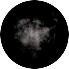
The sCloud texture simulates clouds, but can also be used to create steam, smoke, or fire effects.

Note the following when using the sCloud texture:
- You should only map the sCloud texture to a sphere. The sphere can be transformed in any way (for example, non-proportionally scaled), as long as the actual base component is a sphere. You can combine several spheres to create complex cloud arrangements. If you map the sCloud texture to any other type of surface, the results will be unpredictable.
- The area surrounding the cloud is always transparent, regardless of the type of mapping used.
- You can also create smoke and fire effects using lights with fog and 2D noise, or with particles.
Cloud Effects
To create a cloud using the sCloud texture, create a new shader and set the shader parameters as follows:
- Set Shading Model to LAMBERT
- Set Color to white (or grey for smoke)
- Set the Refractive Index value to 1
- Map Transparency with an sCloud texture.
Transparency is a 3-channel (RGB) mapping. As a result, the sCloud texture requires additional settings to work properly as a transparency map. Set the sCloud parameters as follows:
- Set Color1 and Color2 to white
- Adjust the Transp_range value to make the cloud more dense.
Apply the shader to a sphere.
Flame Effects
To create flames using the sCloud texture, create a new shader and set the shader parameters as follows:
- Set Shading Model to LIGHTSOURCE
- Set the Refractive Index value to 1
- Set Transparency to its maximum setting (white)
- Set the Glow value to 0.5
- Map Incandescence with an sCloud texture.
Set the sCloud parameters as follows:
- Set Color1 to pure green and Color2 to pure red
- Set the Transp_range value to 0.3
- Set the Center_thresh value to -0.5
- Set the Amplitude value to 2
- Set Rgbmult to a Value of 2.
Apply the shader to a sphere or an elongated (non-proportionately scaled) sphere. Non-proportionately scale the sCloud texture's Object Placement Object to create a more vertical looking flame.
To simulate smoke, use the cloud example above to create a shader, set the shader Color to black, and apply the shader to an elongated sphere positioned above the flame sphere. Animate the transformation icon slowly upwards.
To create an explosion effect, animate the sphere being scaled up.
To create a roaring fire, animate the transformation icon for the texture, moving it upward at a constant rate.
Glow Effects
To create glows using the sCloud texture, create a new shader as described above to create flame effects. Set the sCloud texture's Amplitude value to 0, assign the shader to a sphere, and put the object that you want to glow inside the sphere.
sCloud Texture Parameters

Color1, Color2
-
- The two colors that are blended together to form the cloud.
Contrast
-
- The contrast between Color1 and Color2. For example, if the Contrast value is -1, Color1 and Color2 are reversed. The slider range is 0 (the two colors are averaged over the entire texture) to 1. The default value is 0.5.
Edge Rolloff Parameters
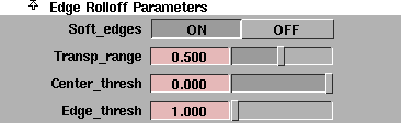
The Edge Rolloff Parameters determine how the texture's transparency changes as the surface it is mapped to turns away from the camera.
|
|

|
Soft_edges
-
- Gradually increases the transparency of the texture as the surface it is mapped to turns away from the camera. This simulates natural looking clouds. If Soft_edges is OFF, the texture is entirely opaque, and appears similar to the sFractal texture. The default setting is ON.
|
|
|
Transp_range
-
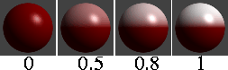
- The range over which the texture becomes transparent. The Transp_range value controls the sharpness/softness of the edges of the cloud. The valid range is 0 to ·. The slider range is 0 (sharp edges) to 1 (very soft edges). The default value is 0.5.
|
|
|
Center_thresh, Edge_thresh
-
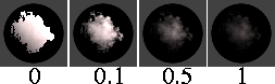
- Determines how diffuse or concentrated the edge rolloff is. If the Center_thresh value is low and the Edge_thresh value is high, the texture will resemble a dense cotton-ball. If the Center_thresh value is high and the Edge_thresh value is low, the texture will resemble a wispy cloud. The slider range is -1 to 0 for Center_thresh and 1 to 2 for Edge_thresh. The default value is 0 for Center_thresh and 1 for Edge_thresh.
Noise Parameters

The Noise Parameters control the fractal noise used to generate the sCloud texture.
|
|
|
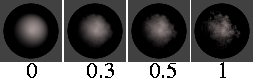
Amplitude
-
- Controls the strength of the fractal noise used to generate the sCloud texture. The valid/slider range is 0 (no noise) to 1 (strong noise). The default value is 1.
|
|
|
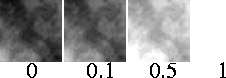
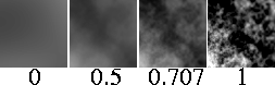
Ratio
-
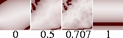
- Controls the frequency of the fractal noise used to generate the sCloud texture. The slider range is 0 (low frequency) to 1 (high frequency). The default value is 0.707.
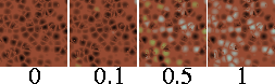
sFractal Texture
|
|
|
|
| |
|

|
The sFractal texture represents a three dimensional random function with a particular frequency distribution (a fractal) and can be used to create many different types of effects.
sFractal Texture Parameters

|
|
|
Threshold
-
- An offset factor applied to all values in the texture. The valid range is 0 to ·. The slider range is 0 to 1. The default value is 0.
|
|

|
Amplitude
-
- A scaling factor applied to all values in the texture about the texture's average value. The valid range is 0 to ·. The slider range is 0 (no noise) to 1 (strong noise). The default value is 1.
|
|
|
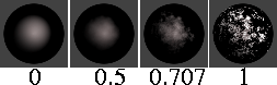
Ratio
-
- Controls the frequency of the fractal noise. The valid/slider range is 0 (low frequency) to 1 (high frequency). The default value is 0.707.
sMarble Texture
|
|
|
|
| |
|
|
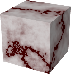
The sMarble texture simulates marble: a vein material sandwiched between layers of filler material, where the vein material diffuses into the filler material.
sMarble Texture Parameters
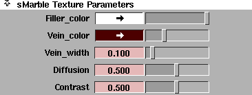
Filler_color, Vein_color
-
- The color of the filler material and the vein material.
|
|

|
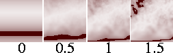
Vein_width
-
- The thickness or width of the veins. The slider range is 0 to 1. The default value is 0.1.
|
|
|
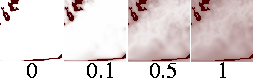
Diffusion
-
- Controls the amount that the Vein_color blends into the Filler_color. (The Contrast value also affects how the two colors blend together.) The slider range is 0 (no blending) to 1 (smooth blending). The default value is 0.5.
|
|
|
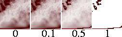
Contrast
-
- The contrast between the Vein_color and Filler_color. The slider range is 0 to 1. The default value is 0.5.
Noise Parameters

The sMarble texture creates a three dimensional texture by projecting a two dimensional texture. The Noise Parameters control the randomization (using fractal noise) of the texture in the direction the texture is projected.
|
|
|
Amplitude
-
- A scaling factor applied to all values in the fractal noise about the average value. The valid range is 0 to ·. The slider range is 0 (no noise) to 1 (strong noise). The default value is 1.5.
|
|
|
Ratio
-
- Controls the frequency of the fractal noise. The valid/slider range is 0 (low frequency) to 1 (high frequency). The default value is 0.707.
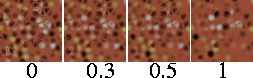
sRock Texture
|
|
|
|
| |
|

|
The sRock texture simulates rock using a random, three dimensional distribution of two different types of grain material.

sRock Texture Parameters

Color1, Color2
-
- The color of the two types of grains in the texture.
|
|
|
Grain_size
-
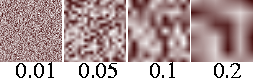
- The size of grains in the texture. The Grain_size value effectively scales the entire texture. The valid range is 0 to ·. The slider range is 0 (no grains) to 0.1 (large grains). The default value is 0.01.
|
|
|
Diffusion
-
- Controls the amount that Color1 blends into Color2. The valid range is 0 to ·. The slider range is 0 (no blending) to 1 (smooth blending). The default value is 1.
|
|
|
Mix_ratio
-
- Determines which of the two colors is the dominant color. The valid range is 0 to ·. The slider range is 0 (Color1 is totally dominant) to 1 (Color2 is totally dominant). The default value is 0.5.
Leather Texture
|
|
|
|
| |
|

|
The Leather texture simulates leather, but can also be used to simulate other materials, including alligator skin, Styrofoam, and concrete, particularly when used as a bump map.

For many situations, an image file of real leather will produce a good leather simulation. However, it is often impossible to map a file texture to a surface without distortions and discontinuity. Chord Length or Worldspace texture mapping may eliminate distortions, but they require some effort and do not always work. In these cases, use the Leather texture.
The Leather texture uses a three-dimensional array of spheres to simulate two-dimensional leather. This is unlike real leather because real leather is a surface, not a solid. However, the Leather texture usually produces very realistic results. One exception is if the surface is deformed during an animation, because the surface will appear to move through the solid texture. In this case, however, you can convert the solid texture to a File texture (see Converting a Solid Texture to a File Texture on page 184).
Leather Texture Parameters
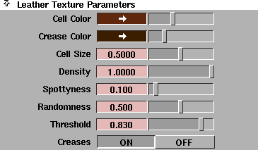
Cell Color, Crease Color
-
- The color of individual cells (Cell Color) and the medium surrounding the cells (Crease Color).
|
|

|
Cell Size
-
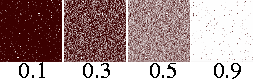
- The size of individual cells. The Cell Size value effectively scales the entire texture. The valid range is 0 to ·. The slider range is 0 to 1. The default value is 0.5.
|
|
|
Density
-
- Controls the spacing of cells in the texture. The valid range is 0 to ·. The slider range is 0 to 1 (fully packed). The default value is 1.
|
|

|
Spottyness
-
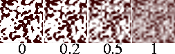
- Randomizes the Cell Color intensity. (The Threshold value also influences the Cell Color intensity.) The valid range is 0 to ·. The slider range is 0 (all cells have the same intensity) to 1 (cell intensity is entirely random). The default value is 0.1.
|
|
|
Randomness
-
- Randomizes cell position. The valid range is 0 to ·. The slider range is 0 (cells are arranged in a regular 3D lattice) to 1 (cell location is entirely random). The default value is 0.5.
|
|
|
Threshold
-
- Controls how much the Cell Color and Crease Color mix into each other. The valid range is 0 to ·. The slider range is 0 to 1 (no mixing, cells appear as solid color dots). The default value is 0.83.
|
|
|
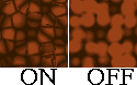
Creases
-
- Creates boundaries between cells that resemble the creases in leather. If Creases is OFF, the cells diffuse uniformly into each other. The default setting is ON.
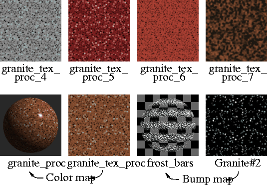
Granite Texture
|
|
|
|
| |
|

|
The Granite texture simulates granite using a random, three dimensional array of three different types of spheres suspended in a medium. The Granite texture is essentially the same as the Leather texture, except that there are three cell colors instead of one.
The Granite texture is very time consuming to render. Convert it to a File texture whenever possible (see Converting a Solid Texture to a File Texture on page 184).
Granite Texture Parameters
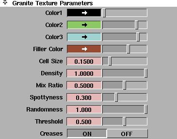
Color1, Color2, Color3, Filler Color
-
- The color of the three different types of cells (Color1, Color2, Color3) and the medium surrounding the cells (Filler Color).
|
|
|
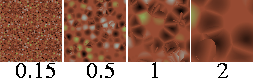
Cell Size
-
- The size of individual cells. The Cell Size value effectively scales the entire texture. The valid range is 0 to ·. The slider range is 0 to 1. The default value is 0.15.
|
|
|
Density
-
- Controls the spacing of cells in the texture. The valid range is 0 to ·. The slider range is 0 to 1 (fully packed). The default value is 1.
|
|
|
Mix Ratio
-
- Determines which of the three colors is the dominant color. The valid/slider range is 0 (Color1 is dominant) to 1 (Color3 is dominant). The default value is 0.5 (Color2 is dominant).
|
|
|
Spottyness
-
- Randomizes the cell color intensity. (The Threshold value also influences the cell color intensity.) The valid range is 0 to ·. The slider range is 0 (all cells have the same intensity) to 1 (cell intensity is entirely random). The default value is 0.3.
|
|

|
Randomness
-
- Randomizes cell position. The valid range is 0 to ·. The slider range is 0 (cells are arranged in a regular 3D lattice) to 1 (cell location is entirely random). The default value is 1.
|
|

|
Threshold
-
- Controls how much cell colors and filler color mix into each other. The valid range is 0 to ·. The slider range is 0 to 1 (no mixing, cells appear as solid color dots). The default value is 0.5.
|
|

|
Creases
-
- Creates boundaries between individual cells. If Creases is OFF, the cells diffuse uniformly into each other. The default setting is ON.
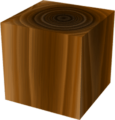
sWood Texture
|
|
|
|
| |
|
|
The sWood texture simulates wood by projecting a two dimensional pattern. This pattern consists of layers or concentric rings defined by veins and filler. When you map the sWood texture to a surface, the surface will appear to be carved out of wood. If you map the sWood texture to several surfaces, they will appear to be carved from a single block of wood.
|
|

|
sWood Texture Parameters
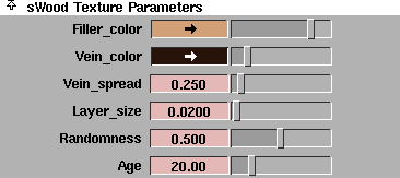
Filler_color
-
- The color of the space between veins. The vein color diffuses into the filler color.
Vein_color
-
- The color of veins in the wood. The vein color diffuses into the filler color.
|
|

|
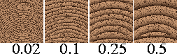
Vein_spread
-
- The amount that the vein color diffuses into the filler color. The valid range is 0 to ·. The slider range is 0 to 3. The default value is 0.25.
|
|
|
Layer_size
-
- The average thickness of each layer or ring. (The thickness of individual layers or rings is also influenced by the Randomness and Age values.) The valid range is 0 to ·. The slider range is 0 to 0.5. The default value is 0.02.
|
|

|
Randomness
-
- Randomizes the thickness of individual layers or rings. The valid/slider range is 0 to 1. The default value is 0.5.
|
|

|
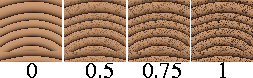
Age
-
- The age (in years) of the tree from which the wood came. The Age value determines the total number of layers or rings in the texture, and influences the relative thickness of central and outer layers. The central rings of wood are thinner than the outer rings because a trees' growth is slower when it is young. The valid range is 0 to ·. The slider range is 0 to 100. The default value is 20.
Grain Parameters (spots)

The Grain Parameters (spots) control the appearance of random grain in the wood (which appears as spots in the texture's cross-section).
Grain_color
-
- The color of the random grain in the wood.
|
|
|
Grain_contrast
-
- Controls the amount that the Grain_color diffuses into the surrounding wood color. The valid/slider range is 0 to 1. The default value is 1.
|
|

|
Grain_spacing
-
- The average distance between grain spots. The valid/slider range is 0.002 to 0.1. The default value is 0.01.
Concentric Ring Location

|
|

|
Center_u, Center_v
-
- The location of the center of the texture's concentric rings in the U and V parametric directions. The slider range is -1 to 2. The default value is 0.5 for Center_u and -0.5 for Center_v.
|
Tip:
|
Don't set the Center_u or Center_v value less than -3 or
greater than 3.
|
Noise Parameters
The sWood texture creates a three dimensional texture by projecting a two dimensional pattern. The Noise Parameters control the randomization (using fractal noise) of the texture in the direction the pattern is projected.
|
|

|
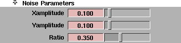
Xamplitude, Yamplitude
-
- A scaling factor applied to all values in the fractal noise about the average value, in the texture's X and Y directions. The sWood texture will render faster if the Xamplitude and Yamplitude values are both 0. The valid range is 0 to ·. The slider range is 0 (no noise) to 1 (strong noise). The default value is 0.1.
|
|

|
Ratio
-
- Controls the frequency of the fractal noise. The valid/slider range is 0 (low frequency) to 1 (high frequency). The default value is 0.35.
Volume Texture
|
|
|
|
|
The Volume texture allows the Ball texture to use multiple image files. If you map a File texture to the Ball texture's Image parameter, the Ball texture can only use a single image file and the texture will have a "pinch point" or bad spot. If you map a Volume texture to the Ball texture's Image parameter, the Ball texture automatically selects the "best" image file (for the current view) from the sequence of image files specified in the Volume texture. The "best" image file for a particular view is the one whose bad spot is furthest away.
You can use the Volume texture to specify any number of image files, although 32 is a reasonable maximum.
Volume Parameters

From, To
-
- The extension number of the first (From) and last (To) file in the sequence. The valid range is 0 to ·. The slider range is 1 to 16. The default value is 1.
Pix Sequence
-
- The name of any image file in the sequence (for example, pixfile.4).
|


