|
|
10
|
Solid Textures
|
|
Solid textures are three-dimensional patterns that simulate solid materials (for example, wood or marble) by either using an image file or series of image files (Projection and Volume textures) or using a computer graphic procedure (Snow, sCloud, sFractal, sMarble, sRock, Leather, Granite, and sWood textures). When you map a solid texture to a surface, the surface will appear to be carved out of that material.
In This Section:
Using Solid Textures
|
|
|
|
|
Typically, you use solid textures to make an object appear to be carved out of a block of solid material (for example, wood or marble). Solid textures determine the color of a surface based on the XYZ values of each point on the surface. Solid textures are, therefore, not affected by the parameterization of a surface, and will not distort (the way a surface texture will) when mapped to a surface with uneven parameterization.
Converting a Solid Texture to a File Texture
One of the disadvantages of using a solid texture is apparent during animation. When you animate a surface that is mapped with a solid texture, the surface will appear to flow through the solid material. One method of solving this problem is to convert the solid texture into a File texture.
To convert a solid texture into a File texture:
-
1
-
Pick the surfaces you want to create a new shader for.
-
2
-
In the Multi-lister, pick the shader for the selected surfaces.
-
3
-
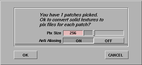
Select Edit > Convert Solid Tex in the Multi-lister. A dialog box appears.
-
The default value for Pix Size is 256 pixels square. Image
files are created and sized so that the Pix Size corresponds
to the longest dimension of the largest selected surface. If
more than one surface is selected, the other image files are
proportionally smaller. The valid range is 8 to 1024 pixels.
|
Tip:
|
Larger image files require more memory to render, and
depending on the render specifications, may not noticeably
improve render quality. Anti Aliasing is recommended in
most circumstances, but Convert Solid Tex will take four
times longer than if Anti Aliasing is OFF.
|
|
Note:
|
Convert Solid Tex places the newly generated image files in
a sub-directory (that has the same name as the shader being
converted) in the pix directory of the current project.
|
-
4
-
Click OK. Information is displayed in the information line.

-
The progress bar at the far right indicates the status of the
current pix creation.
Solid Texture Parameters
|
|
|
|
|
The Color Balance, Intensity, Blur, Effects, Recursion Depth, Solid Noise Frequencies, and 3D Placement parameters are common to most solid textures.
Color Balance, Intensity, Blur, Effects
See Texture Parameters on page 101.
Recursion Depth

|
|
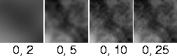
|
Level_min, Level_max
-
- The minimum and maximum number of iterations used to calculate the texture pattern. This parameter controls how fine grained the texture is. The slider range is 0 to 25. The default value is 0 for Level_min and 20 for Level_max.
|
Tip:
|
If both Level_min and Level_max are high (close to 100),
rendering will take a long time. If you want to make the
fractal pattern more finely grained, lower Blurmult or Amult
instead.
|
Solid Noise Frequencies
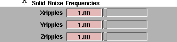
|
|
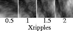
|
Xripples, Yripples, Zripples
-
- Determines how wavy the texture is in the X, Y, and Z directions. These parameters represent the scale of the fundamental frequency of the fractal used to generate the texture. The slider range is 0 to 20. The default value is 1.
|
Note:
|
The Projection texture has an extra Solid Noise Frequencies
parameter called Stagger.
|
3D Placement
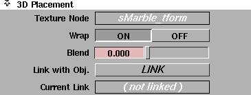
The 3D Placement parameters control the orientation of the solid texture relative to the surface it is mapped to.
Texture Node
-
- The name of the Texture Placement Object. See Texture Placement Objects on page 96.
|
Tip:
|
The Texture Placement node is easier to find in the SBD
window if you know its name.
|
|
|
|
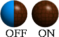
Wrap
-
- Repeats the texture outside the region defined by the Texture Placement object. If Wrap is OFF, the texture only appears on a surface inside the region defined by the Texture Placement object. The default setting is ON.
|
|
|
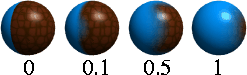
Blend
-
- Gradually blends the texture into the (unmapped) value of the shader parameter being mapped. The blend region is defined by the boundaries of the Texture Placement Object. For example, if a Leather texture is bump mapped onto a surface, and Blend is greater than zero, the bump will gradually diminish as it reaches the boundaries of the Texture Placement Object. If Blend is set to 0, the texture ends abruptly at the boundaries defined by the Texture Placement Object. The slider range is 0 (no blend) to 1 (very gradual blend). The default setting is 0.
|
Tip:
|
Blend works best if Wrap is OFF. If Wrap is ON, the texture
will blend into the (unmapped) value of the shader
parameter being mapped at the boundary of the Texture
Placement Object and repeat infinitely as the texture is
repeated.
|
Link with Obj.
-
- Links the texture to the active object it is mapped to so that the texture undergoes the same transformations (except cluster and CV deformations) as the object. To link the texture to an object, pick the object and click the LINK button. The name of the object is displayed in the Current Link field.
|
Note:
|
You can only link a texture with one object (one DAG or
hierarchy).
|
Current Link
-
- The name of any object that you have linked to the texture using Link with Obj.
|


