Home
My Airplanes
Where I used to fly
R/C Sukhoi 26mx
Other People's Sukhois
Download
View Guestbook
Sign Guestbook
Copyright notice
Links page
About Me
Stuck in someones frames? Click here to escape.
Website maintained by Erik Middeldorp
| ||||||||
|


These notes are ment to help experienced builders.
[December 2001: Alex Kolyvanov has offered to laser cut the parts, so you may want to investigate this option as it could save a lot of work. He has also offered to print the plans. See the link on the Sukhoi Intro page]
TAILPLANE
 Remember to remove the pins from the inside ribs of the tailplane before sheeting the first side, otherwise you'll have a hell of a time getting it off the building board. I taped the LE of the sheet down with masking tape and used a few old magazines to weigh the sheeting down, it works ok but you have to be careful that the trailing edge dosn't get bent [from too much weight]. Make sure you remember to add the hinge blocks before sheeting both sides of the tailplane. I didn't and it was a real pain trying to get them in later. Jig the tailplane up with some scrap balsa and make sure it is really flat before sheeting the 2nd side. Tack glue the elevator tip blocks on and get them roughly to shape, then remove them and hollow them out before permanently glueing them in place (glue the tips on permanently and finish shapeing them before separating the elevators). When separating the elevators from the tailplane hold the tailplane infront of a bright light to see the outline of the ribs. Add a small amount (I used one layer of 3/4oz. cloth) of fibre glass to the centre section of the tailplane, top and bottom.
Back to the top
FIN
Pretty much the same as the tailplane.
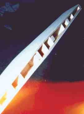
WING
 When cutting out the wing ribs, don't cut out any of the tab side notches for the 3mm spar and only the ones from W1 to W7 for the 6mm by 3mm spar. After cutting out the ribs, I started construction by pinning the 6.5mm square spruce spars onto the building board on the front view of the wing and then gluing the 1.5mm ply wing root brace on the top side with epoxy. Be carefull not to let any excess epoxy set on the insides of the spars as this area is going to house the wing joiner. When the epoxy had set, I removed the spar from the plan and glued the 1.5mm brace on the other side, once again being careful with the epoxy. I don't know if it's necassary but I pinned the spar/wing-brace assembly in three places with toothpicks.
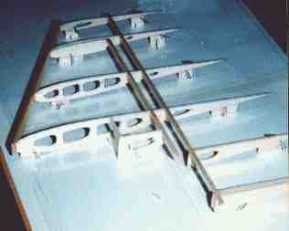
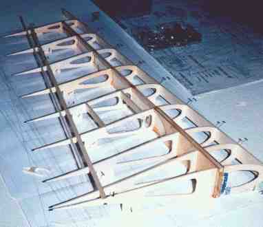
 Now you can pin the spar assembly to the plan and slide the ribs into place. The wing is built with the spar flat on the board to reduce the size of the rib jig tabs and save balsa. This means that the ribs need to be angled relative to the building board (there is a rib angle guide thing on the plan, cut it out of cardboard and use it). Do not omit the sheer webs as they add considirable strength to the wing. The rest of the construction is very simular to the Tailplane/Fin assemblies. Make sure you remember to add the sub ribs on the aileron, the hinge blocks and the wing bolt bracket and blind nut before sheeting the second side. When I got the wing fully sheeted and the leading edge, wing tip and trailing edge shaped/cut to size, I cut the aileron out and trimmed and
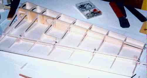
 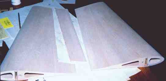 sanded the edges of the aileron and wing so that they were ready to accept their LE and TE. I had marked the positions of the hinge blocks on the sheeting but managed to sand them off when I was shapeing the leading and trailing edges of the ailerons and wing. I held the aileron up to a bright light so that I could see the hinge block positions and I marked them that way, but I didn't check the wing as well and ended up drilling a couple of the hinge holes in the wrong places.
Back to the top More pictures of the wing construction
FUSELAGE
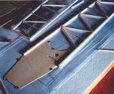 I started the fuselage by framing up the 6.5mm thick sides. Once the two sides were done and removed from the plan, I pinned one of the 1.5mm ply doublers (marked on the plan as "engine box sides") over the fuselage side view, and glued one of the fuselage frames onto it, making sure that it lined up with the plan properly. When the glue dried, I flipped the frame and doubler so that the ply was on top. I supported the middle of the doubler with some 6.5mm scraps and lay the second doubler on top of it and pinned them down so they wouldn't move and then glued the second piece of frame to the doubler using the first frame to line everything up. After the frames and doublers are joined, add
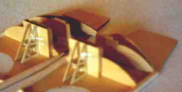 the 1.5mm ply landing gear strengtheners followed by formers F3, F6B and F7B (the plywood that I used for the formers was 3.3mm Ivorywood exteriour ply which was reasonably light. Light ply would probably work too but I've never used it before. Basically I think you should use a lightweight plywood of some sort.). Be very careful when glueing F7B in place as it forms part of the wing joiner box and has to be at 90 degrees to the doubler to line up properly. The wing joiner box is made up over the plan by pinning two pieces of 6.5mm square spruce onto the plan view of the wing joiner box and then glueing the 1.5mm ply on top of them. I made the two boxes in one piece to help keep things accurate. Before I attached the boxes to the fuselage sides I removed the excess glue from the insides of them. I added the wing
 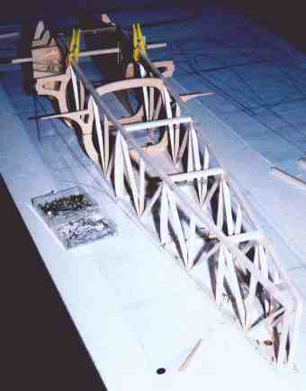 retaining bolt braces to the fuselage sides now as well. Time to join the fuselage sides. First cut out the 2.5mm balsa cockpit floor and trim the 6.5mm balsa cross pieces (make two of each cross piece for the top and bottom of the fuselage) and pin them in place on the top view of the plan. Mark on the fuselage sides where the cross pieces and cockpit floor meet the frame then take formers F8B and F10 and check that they fit properly. Now glue it all together. I put some glue on the two formers and got them in place on the
 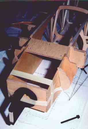 fuselage sides and then lowered the sides and formers onto the top view of the plan as one piece. If your plan is strait then your fuselage will be too. I used pins to hold the fuselage sides against the cross pieces etc on the plan and I used sticky tape to hold the sides together at the top. Mark and drill the holes in the landing gear plate and firewall and glue the blind nuts in place. I glued the landing gear plate in the fuselage first (and also pinned it with a toothpick at the front of each side), then the firewall and finally the 1.5mm ply engine box bottom. After that I was able to add F2 and F4 and the rest of the lower fuselage formers. I added a couple of bits of balsa to fill the gaps between the landing gear plate and the fuselage sheeting. Add the 1.5mm ply wing fairing formers and the 3mm balsa wing stub ribs (F16) then start sheeting. I sheeted the back of the fuselage first, but in hindsight I think it would have
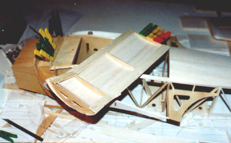 been easyer to sheet the hatch first. The hatch is sheeted with two seperate pieces of 2.5mm balsa starting with the rear piece. Before removing the fuselage from the building board, I finished sheeting the bottom of the fuselage down to where the wing stubs join the fuselage. After I had removed the fuselage from the building board, I reinforced the inside of the engine box with some 9.5mm balsa tri-stock and then glued the 1.5mm ply top in place. When it was dry
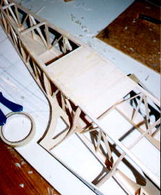 I added the tri-stock to the remaining corners of the engine box. The fuselage sides form a sharp bend at the rear of the canopy. The easiest and strongest way that I could think of to do this is to let the 6.5mm side frames form a curve and then laminate some extra balsa on the sides carving it to the angle needed. Use a couple of 6.5mm x 2.5mm balsa strips on either side.
Before any more sheeting is done I suggest that you decide where you want to mount the elevator and rudder servos and make the mounts. Click here to jump to the bit on servo installation.
Time to glue the top fuselage formers in place. The formers for the rear turtle deck have a single 6.5mm x 3mm balsa stringer connecting the tops of each former, the main reason for this is to ensure that F12 stays at the right angle when the sheeting is applied. The sheeting for the rear turtle deck was made by gluing 4 pieces of balsa together along the edges to form a sheet and then attached in one piece. To get the balsa to conform to the formers (the rear former in particular) I steamed it, but the joints between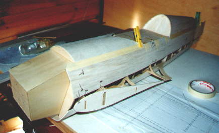 the balsa opened up a bit in one place. I think if I was to do it again I would use packing tape on the outside of the sheeting, this way it can be bent around really tight corners without splitting, and then just remove the tape after the sheeting was glued in place. The front fuselage sheeting was easier to glue as it has to conform to a shallower curve.
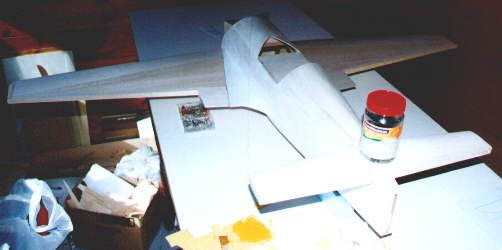
Ok, it is finally starting to look like a sukhoi! Woo hoo.
Sheeting the sides. I used a sheet of 2.5mm x 75mm x 915mm balsa and cut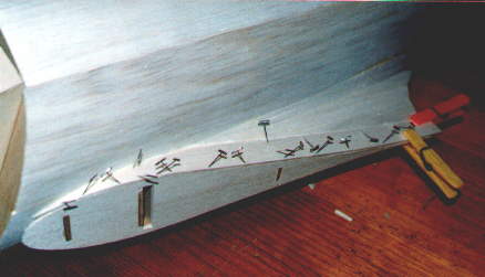 just a bit out of the top edge to get it to fit against the top fuselage sheeting and then glued it in place. I did one side at a time because the fuselage has to be held on its side and I didn't want to disturb the sheeting while the glue was drying. When both sides are done, you just have to add a strip to fill the gap between the top and bottom sheeting and then you can move on to sheeting the wing fillets. I suggest that you sheet the top side of the wing fillet first as it is the more difficult of the two sides and it helps to have access to the sheeting from the bottom. I wasn't too worried about getting the top fillet planking to fit perfectly, as long as there aren't any significant
 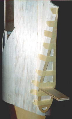 gaps between the strips of balsa it should be ok. You'll just have to use a bit more balsa filler later. For the bottom of the wing stub/fillet you can use a single piece of balsa (grain parallel to fuselage) to sheet from the back right up to F6B and then use a small piece of balsa, with the grain spanwise to sheet the remaining gap. Tack glue the 1.5mm plywood wing stub ribs (F17) on to the wings and sand their edges flush with the wing surface. Cut the hole for the wing joiner and drill the hole for the wing alignment pin while F17 is still tack glued to the wing. Once they have been shaped and the nessasary holes have been cut out, you can remove them from the wings. When you glue them in place on the fuselage, make sure that they are aligned correctly as they set the wings incedence.
Back to the top More pictures of the fuselage
LANDING GEAR
I made the landing gear out of fibreglass, this is the second time I have used fiberglass landing gear. It is fairly simple to 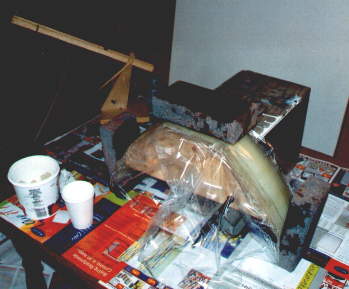 do, first of all cut out the LG former out of 9mm (3/8") plywood. Then get some cardboard and cut it to the shape you want the landing gear to be and glue it to the ply former. I needed to laminate two thicknesses of cardboard together for strength. Next get some 9oz fiberglass cloth and cut out 12 strips that are the full length of the LG and that over-hang by about 20mm, 2 strips that go 2/3 of the way down each leg and two more that go about 1/3 of the way down. Then get two pieces of polythelene (the backing stuff from iron on films eg. monocote, solarfilm) that are big enough to cover the largest pieces of fibreglass
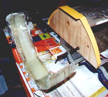 with a healthy overhang. Now just build up a sandwich of glass cloth and resin on one of the pieces of polythene and when it is complete cover it with the second piece of polythene. Get a block of wood and squash the fibreglass polythene sandwich so that the exess resin gets squeezed out. Once all that is done, you just have to drape the fibreglass sandwich over the LG former thing and let it set. I used a couple of blocks to hold the fibreglass in place near the ends of the LG and also a piece of ply on top of it to keep the top flat. When the epoxy has set, cut the LG out and sand it to the final shape. Drill the holes for the mounting screws and axles (I used Dubro axles but I think next time I might try something lighter) and then give it another coat of epoxy to seal it.
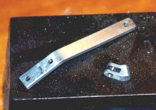 The tailwheel bracket was made out of some scrap aluminium. The plans and photos are pretty self explanitory. No special tools are needed to make it, just a file, hacksaw, drill and a bench vice. And I think the final result looks pretty good.
FINAL ASSEMBLY
 To join the tailplane to the fuselage first I glued in some scrap balsa to build up the tailplane seat. To help align the tailplane properly I attached the wings and then propped the fuselage and wings up on the building board so that they were level with the top of the building board. Then I made a small cardboard cut out and trimmed it so that it was the right shape for the tailplane seat, checking it with the tailplane as I went along. I measured how high relative to the building board the tailplane had to be and then I made a cardboard support so that when the bottom of the support was on the building board it would hold the tailplane seat template thing at the right hight and incedence. Using this method I was able to mark on the side of the fuselage where the tailplane seat had to be and then use a dremel with a sanding drum to sand the tailplane seat down to this mark. I glued the tailplane on with slow setting epoxy so that I could take some time to get it aligned correctly. Also if there were any small gaps the epoxy would fill them. When the epoxy had set, I trimmed and sanded the fin and then used PVA to glue it in place. I used some scrap balsa and filler to make the fin/elevator/fuselage fairing.
Update 9th October 2000: Something I forgot to mention, on my sukhoi I have a small amount of down elevator trim set to maintain level flight. I think that with a forward cg it might not need any down trim, but if you plan on using a more rearward cg you might need some, and it could be beneficial to build some positive incedence into the tailplane strait off. But I don't have an incedence meter to check how much would be needed.
THE COWL
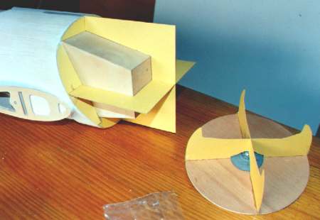 I made some cardboard formers and temporarily stuck them to the firewall and then I filled the gaps with polystyrene. The front part of the cowl was made by using a 3mm ply circular disk and glueing cardboard formers and polystyrene to it and then attaching it to the electric drill (because I don't have a lathe) and sanding it to shape on that. After I sanded the cowl plug to shape and removed it from the fuselage, I covered it with packing tape. I used my covering iron to shrink out the rinkles around the front of
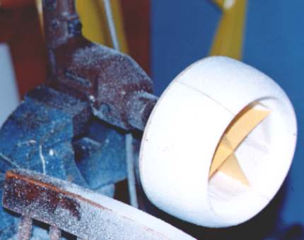 the plug (that brown packing tape shrinks at quite low temperature lower than like covering film). Then I mounted the cowl plug pointing nose up and covered it with two layers of 3 oz fibreglass cloth. After that had set I gave it a coat of resin to fill the weave (I didn't have any microballoons to mix in but I think they would have helped reduce the weight a little) and then sanded it till it was smooth enough to paint. I had to be careful sanding over the places where the cardboard formers were under the fibreglass so that I didn't sand thin spots in the cowl.
CANOPY
I made the canopy mould out of several layers of medium density 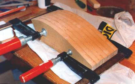 fibreboard (customwood). It was given three coats of epoxy and a fair bit of sanding to get it really smooth. The final coat was sanded with 600 grit wet and dry paper. Airsail vacuum formed a canopy over my mould but it had a few small bumps and join lines (from the custom wood). I had to fill the canopy with plaster bedding compound which, once dry, left me with another plug needing more sanding and coating with sanding sealer. The second canopy, moulded from the plaster plug, was not a lot better than the first but at least it didn't have the join lines from the customwood moulded in to it.
PILOT
 For the pilot I wanted to carve one that looked like me, so I got some blue foam that I had lying around and got a side view and font view of my head and started carving away. I was surprised how hard it is to carve a bust that looks right, what I ended up with didn't look a lot like me. I had intended to glue the hair on to him so I carved him bald. I tried glueing some wool to his head to simulate hair... The result was that it looked like he had wool glued to his head. By now I had given up trying to make it look like me so I pulled the "hair" off and made him a hat. At least it dosn't look like all the other model pilots out there.
SERVO INSTALLATION
I assembled as much of the plane as I could (including: engine, muffler, engine mount, cowl, prop, spinner, landing gear, wings, fuel tank, all control surfaces and the pilot and canopy) and then checked where it balanced and changed the servo positions to get the balance point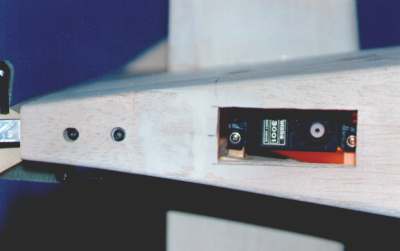 about right to avoid adding lead later. I mounted the rudder servo up-side down, under the tailplane. Because I was using a forked (Y) pushrod for the two elevator halves I wanted to mount the elevator servo on it's side so that I didn't end up with differential elevator travel. I had to mount the elevator servo just behind the cockpit so that I could have the servo on it's side and keep the control horn lined up with the middle of the fuselage. I would strongly suggest that you decide on where you are going to mount your servos before you sheet the top of the fuselage as it is quite tricky working inside the fuselage through the hatch. I made the elevator servo mounting rails strong enough so that if I have to I can mount the battery and/or reciever above it. The aileron servos mount on to the inner side of the hatch with only part of the servo horn showing through.
If you jumped here from the fuselage construction, click here to get back to where you were.
FINAL FINISHING STUFF
For the tailwheel fairing I made an aluminium plate that bolted on under that tailwheel assembly using the bolts that hold the tailwheel assembly in place. I then glued bits of balsa on to the aluminium plate and sanded them to blend in with the fuselage.
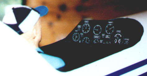 For the instrument panel in the cockpit I thought I would make a polystyrene form and then sheet that with balsa but I ended up making a sort of floor and then a simple dashboard out of thin balsa sheet.
Back to the top Back to the Sukhoi page.