MY 11 TRISECTION APPROXIMATION METHODS Pg. 16
|
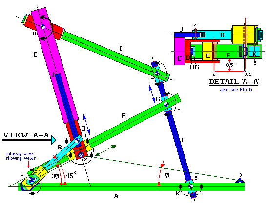
FIG. 3
|
|---|
|
1.
|
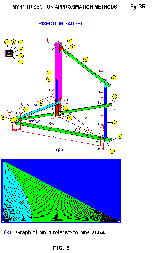
Most arms in FIG. 3
are hollow square tubing that fit inside each
|
|---|
|
|
|
|---|
|
|
other with a slip fit. Ends are built up for proper height or width.
|
|---|
|
|
|
|---|
|
2.
|
The left end of arm A is hinged at pin 1 to arm F and welded to
|
|---|
|
| Pg. 17
|
|---|
|
|
arm B at 45o; the middle is hinged to arm H through hinge 5;
|
|---|
|
|
|
|---|
|
|
and the right end is welded to pin 3, see FIG. 3 above.
|
|---|
|
|
|
|---|
|
| NOTE:
|
|
|
|---|
|
|
Hinges are 1 or 3 sections of round tubing, with a rod or pin inside,
|
|---|
|
|
|
|---|
|
|
welded to square tubing; while 'pins 1, 2 & 3' are sharp tipped rods
|
|---|
|
|
|
|---|
|
|
extending » 0.5" below model, see VIEW "A - A" in FIG. 3, above.
|
|---|
|
|
|
|---|
|
3.
|
Arm B is welded securely to arm A at 45o and hinged to arm J
|
|---|
|
|
|
|---|
|
|
by hinge 4, as shown in FIG. 3 and in VIEW "A-A" above.
|
|---|
|
|
|
|---|
|
4.
|
Arm C holds a slider arm D and is welded to arm J at one end and
|
|---|
|
|
|
|---|
|
|
hinged to arm I at hinge 0 at the other end, see FIG. 3 above.
|
|---|
|
|
|
|---|
|
5.
|
Arm D slides inside arm C at one end and is welded and hinged at
|
|---|
|
|
|
|---|
|
|
pin 2 to slider E at the other end, as shown in FIG. 3 above.
|
|---|
|
|
|
|---|
|
6.
|
Slider E slides freely over arm F and is hinged at pin 2 to arm D.
|
|---|
|
| Pg. 18
|
|---|
|
7.
|
Arm F is hinged (1) to arm A at one end and slides inside slider E,
|
|---|
|
|
|
|---|
|
|
midway, and hinged (6) to slider G at the other end, see FIG. 3.
|
|---|
|
|
|
|---|
|
8.
|
Slider G is hinged (6) to arm F and freely slides over arm H.
|
|---|
|
|
|
|---|
|
9.
|
Arm H is hinged (5) to arm A at one end, slides through slider G,
|
|---|
|
|
|
|---|
|
|
midway, and is hinged (7) to arm I at the other end, see FIG. 3.
|
|---|
|
|
|
|---|
|
10.
|
Arm I is hinged (8) and built up to fit arm C at one end and is
|
|---|
|
|
|
|---|
|
|
hinged (7) to arm H at the other end , see FIG. 3 above.
|
|---|
|
|
|
|---|
|
11.
|
Arm J is hinged at pin 4 to arm B at one end and welded to arm
|
|---|
|
|
|
|---|
|
|
C, along its centre line,
at the other end, see FIG. 3 above.
|
|---|
|
|
|
|---|
|
12.
|
Arms (J + C), I, H create a machine
linkage or a parallelogram,
|
|---|
|
|
|
|---|
|
|
to keep arms C, I, H parallel to each other, see FIG. 4 below.
|
|---|
|
|
|
|---|
|
13.
|
At the extreme right end of arm A is pin 3 which is located 3 units
|
|---|
|
|
|
|---|
|
|
away from pin 1, see FIG. 4 below.
|
|---|
|
| Pg. 19
|
|---|
|
| NOTE
|
|
|
|---|
|
|
The distance between pin 1 and pin 4 is equal to 0.8965755
|
|---|
|
|
|
|---|
|
|
units and pins' Ð413 =
45o , explained below.
|
|---|
|
|
|
|---|
|
14.
|
Together, the pins 1, 2 & 3 form the angle being trisected:
|
|---|
|
|
|
|---|
|
|
at pin 1 (pins' Ð213 = 3Æ) and the resultant trisection angle at
|
|---|
|
|
|
|---|
|
|
pin 3 (pins' Ð231 » Æ) for all angles of 3Æ, from 0º to 45º, see
|
|---|
|
|
|
|---|
|
|
FIG. 3, above, and FIG. 5b, below.
|
|---|
|
|---|
|
|---|
NOTES FOR FIG. 4 AND FIG. 5b, BELOW:
|
|---|
|
1.
|
FIG. 4 , below, is FIG. 3, above,
with all hinges or pins and their
|
|---|
|
|
|
|---|
|
|
connecting centerlines reproduced exactly.
|
|---|
|
|
|
|---|
|
2.
|
FIG. 5b , below, is FIG. 4, below, with pins 1, 2 & 3 reproduced
|
|---|
|
|
|
|---|
|
|
for all angles.
|
|---|
|
|
|
|---|
|
3.
|
By inspecting FIG. 5b , below,
one can see that the gadget might
|
|---|
|
| Pg. 20
|
|---|
|
|
be more accurate for ÐFOA (pin Ð213 = 3Æ) larger than 45º
|
|---|
|
|
|
|---|
|
|
wherethe drawing approaches a straighter line.
|
|---|
|
|
|
|---|
|
4.
|
Mathematically the hinge (pin 4) attaching arm C to arm B in
|
|---|
|
|
|
|---|
|
|
FIG. 3 can be a 'loose fit'.
|
|---|
|
|
|
|---|
|
5.
|
Arm B could have
been welded further to the right or drilled thru to
|
|---|
|
|
|
|---|
|
|
expose the hinge and pin as long as the distance between pin 1
|
|---|
|
|
|
|---|
|
|
and pin 4 remains 0.8965755 units ie. pins' Ð413 = 45º.
|
|---|
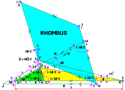
FIG. 4
|
|---|
|
1.
|
Draw any suitable straight line OA = 3 units and the straight line
|
|---|
|
|
|
|---|
|
| OB so that ÐBOA = 3Æ (0o < 3Æ £ 45o), see FIG. 4, above.
|
|---|
|
|
|
|---|
|
2.
|
Locate a suitable pt D on the line OD'B so that ÐD'OA = 3Æ.
|
|---|
|
|
|
|---|
|
3.
|
With a radius length OD' and centre pt O draw an arc across line
|
|---|
|
|
|
|---|
|
|
OC'A at the intersection pt C' just below pt D', see FIG. 4 above.
|
|---|
|
| Pg. 22
|
|---|
|
4.
|
Join pt C' and D' with a
straight line and extend a suitable
|
|---|
|
|
|
|---|
|
|
distance to pt E, see FIG. 4 for guidance.
|
|---|
|
|
|
|---|
|
5.
|
Draw the line OF (pt F is hinge 4), so that ÐFOA = 45o and
|
|---|
|
|
|
|---|
|
|
length OF = 0.8965755 units, as shown in FIG. 4, above.
|
|---|
|
|
|
|---|
|
6.
|
Draw the straight line EFDC parallel to the straight line E'D'C'
|
|---|
|
|
|
|---|
|
|
thus DO = OC through parallelism.
|
|---|
|
|
|
|---|
|
| NOTE:
|
|
|
|---|
|
|
Now pts O, D, & A are pins 1, 2, & 3 respectively, see FIG. 4.
|
|---|
|
|
|
|---|
|
|
Pins' Ð213 = ÐBOA = 3Æ and pins' Ð231 = ÐDAO = Æ
|
|---|
|
|
|
|---|
|
|
Pts D & C are on the lines ODD'B & OCC'A respectively.
|
|---|
|
|
|
|---|
|
|
Pts C', D' & E' are not shown in FIG. 3 or FIG. 4, above; since
|
|---|
|
|
|
|---|
|
|
they represented MATH only.
|
|---|
|
|
|
|---|
|
7.
|
Draw the centerline JG of the mechanical 'arm A', see FIG. 3
|
|---|
|
| Pg. 23
|
|---|
|
|
above, parallel to and below line OA, as shown in FIG. 4 above.
|
|---|
|
|
|
|---|
|
| NOTE:
|
|
|
|---|
|
|
Mathematicallly, pt J could be pt O with pt G a suitable distance
|
|---|
|
|
|
|---|
|
|
on line OGA; however,
the idea is to prove the gadget in FIG. 3.
|
|---|
|
|
|
|---|
|
8.
|
Similarly draw a suitable centerline line JH of 'arm F', see FIG. 3,
|
|---|
|
|
|
|---|
|
|
above, parallel to and above the line OB, with the same offset
|
|---|
|
|
|
|---|
|
|
as JG and call their intersection pt J, as shown in FIG. 4, above.
|
|---|
|
|
|
|---|
|
| NOTE:
|
|
|
|---|
|
|
ÐHJG = ÐDOA = 3Æ by parallel construction, see FIG. 4 above.
|
|---|
|
|
|
|---|
|
9.
|
As in step 3 above; with a suitable radius of length JG and centre
|
|---|
|
|
|
|---|
|
|
pt J draw an arc across the lines JGA and JH, produced, so that
|
|---|
|
|
|
|---|
|
|
JG = JH as shown in FIG. 4, above.
|
|---|
|
|
|
|---|
|
10.
|
Join pts G and H with a suraight line.
|
|---|
|
| Pg. 24
|
|---|
|
|
NOTE:
|
|
|
|---|
|
|
line HG is parallel to line EDC, by construction and parallelism.
|
|---|
|
|
|
|---|
|
11.
|
Take any suitable pt E on line CDFE; with radius length FE and
|
|---|
|
|
|
|---|
|
|
center pt G draw an arc to intersect line
GHI produced, at pt I.
|
|---|
|
|
|
|---|
|
12.
|
Join pts E and I and pts F and G with a straight line.
|
|---|
|
|
|
|---|
|
| NOTE: in FIG. 4
|
|
|
|---|
|
|
Figure FGIE is a parallelogram, by construction and parallelism.
|
|---|
|
|
|
|---|
|
|
and rotates about stationary pts F(4) and G(5) - a MACHINE LINKAGE.
|
|---|
|
|
|
|---|
|
13.
|
Drop a perpendicular from pt F to the meet line OKCA at pt
|
|---|
|
|
|
|---|
|
| K and extend line FK up a suitable distance to pt L, as
|
|---|
|
|
|
|---|
|
|
shown in FIG. 4, above.
|
|---|
|
|
|
|---|
|
14.
|
Similarly drop a perpendicular from pt D to meet the line OKMCA
|
|---|
|
|
|
|---|
|
| at pt M.
|
|---|
|
|
|
|---|
|
15.
|
Thus Ð D'OA = 3Æ and Ð OAD' = Æ' for all positions of pt D' on
|
|---|
|
| Pg. 25
|
|---|
|
|
the line EFD'C - explained later.
|
|---|
|
|
|
|---|
|
16.
|
Thus Ð D'AO = Æ trisects Ð D'OA = 3Æ, as required.
|
|---|
|
|---|
|
|---|
|
|---|
|
|---|
|
|---|
|
1.
|
In DFOA: in FIG. 4
|
|---|
|
|
|
|---|
|
|
Since FK/OK = tan45o = 1.
|
|---|
|
|
|
|---|
|
|
and FK/KA = tan15o = 2 - 3½ = 0.2679492.
[from CRC TABLES]
|
|---|
|
|
|
|---|
|
|
then 3 = OK + KA = FK*((1/tan45o) + (1/tan15o)),
|
|---|
|
|
|
|---|
|
|
thus length OK = FK = 3/((1/tan45o) + (1/tan15o)) = 0.6339746 units.
|
|---|
|
|
|
|---|
|
| NOTE:
|
|
|
|---|
|
|
DM = 3/((1/tan33o) + (1/tan11o)) = 0.44880 = pi/7 = p/7.
|
|---|
|
|
|
|---|
|
|
Can one parallel that; it still meeds a 22 or a 695 NOVA!
|
|---|
|
|
|
|---|
|
|
See http://www.geocities.com/klaus_vanv/nick.htm#nova
|
|---|
|
|
|
|---|
|
|
thus length FO = 0.6339746*2½ = 0.8965755 units.
|
|---|
|
| Pg. 26
|
|---|
|
|
used in construction, as shown in FIG. 3 and FIG. 4, above.
|
|---|
|
|
|
|---|
|
2.
|
In DDOA:
|
|---|
|
|
|
|---|
|
|
Let ÐDOA = 3Æ = 36o and since OD = OC, by construction,
|
|---|
|
|
|
|---|
|
|
then ÐODC = ÐOCD = (180o - 36o)/2 = 72o;
[isosceles D DOC]
|
|
|
|---|
|
|
thus ÐKFC = ÐMDC = 90o - ÐOCD = 90o - 72o = 18o;
[parallel]
|
|
|
|---|
|
|
And thus KC = FK*tan18o = 0.6339746*0.3240167 = 0.2059908 units.
|
|---|
|
|
|
|---|
|
|
therefore OC = OD = OK + KC
= 0.6339746 + 0.2059908 = 0.8399655 units.
|
|---|
|
|
|
|---|
|
|
thus DM = OD*sin36o = Oc*sin36o = 0.8399655*0.7265425 = 0.4937193 units.
|
|---|
|
|
|
|---|
|
|
thus length OM = DM*tan36o = 0.4937193*0.7265425 = 0.6795464 units.
|
|---|
|
|
|
|---|
|
|
and length MA = 3 - OM = 3 - 0.6795464 = 2.3204536 units.
|
|---|
|
|
|
|---|
|
|
therfore, ÐOAD = atan(OM/MA) = 0.4937193/2.3204536 = 12.01161o
|
|---|
|
|
|
|---|
|
|
An ERROR of 100*(12 - ÐOAD)/12
= 0.0967800% - well within limits.
|
|---|
|
|
|
|---|
|
|
Thus ÐOAD = Æ = 12.0o trisects ÐAOD = 3Æ = 36.0o, as required.
|
|---|
|
|---|
|
|---|
|
|---|
|
1.
|
In DDOC:
|
|---|
|
|
|
|---|
|
|
The radii OD = OC make D DOC isosceles and thus ÐODC = ÐOCD =
|
|---|
|
|
|
|---|
|
|
= (180o - ÐDOA)/2 = (2i - 3Æ)/2 = 90o - 3Æ/2 = i - 3Æ/2
|
|
|
|---|
|
2.
|
In DDCA:
|
|
|
|---|
|
|
Since ÐDCA is the complement of ÐDCO, therefore
|
|---|
|
|
|
|---|
|
| ÐDCA = 180o - ÐDCO = 2i - ÐOCD = i + 3Æ/2 and
|
|---|
|
|
|
|---|
|
| ÐCDA = 180o - (i + 3Æ/2) - Æ = i - 5Æ/2.
|
|---|
|
|
|
|---|
|
3.
|
In DOFC:
|
|
|
|---|
|
|
ÐOFC = 180o - 45o - ÐOCD = 2i - i/2 - (i - 3Æ/2) = (i + 3Æ)/2.
|
|---|
|
|
|
|---|
|
4.
|
In DCFK:
|
|
|
|---|
|
|
ÐCFK = 180o- 90o - ÐOCD = 2i - i - (i - 3Æ/2) = 3Æ/2
|
|---|
|
|
|
|---|
|
|
- ie. the bisector of ÐDOC = 3Æ.
[CONSTRUCTION: 2, & 3., Pg. 21]
|
|---|
|
|
|
|---|
|
|
One could have used this angle to get pt D directly.
|
|---|
|
| Pg. 28
|
|---|
|
5.
|
In DHJG & DDOC:
|
|---|
|
|
|
|---|
|
| DHJG is congruent to DDOC; since the sides OD = OC are parallel
|
|---|
|
|
|
|---|
|
| to HJ = GJ = R respectively
- making them both isosceles.
|
|---|
|
|
|
|---|
|
|
Thus ÐJHG = ÐODC = i - 3Æ/2 and thus the bases (HG & DC) of
|
|---|
|
|
|
|---|
|
|
both Ds, or lines IHG and EFDC, are parallel at all times.
|
|---|
|
|
|
|---|
|
6.
|
In figure EFGI:
|
|
|
|---|
|
|
Since EF = IG,
by construction, and since EF and IG are parallel
|
|---|
|
|
|
|---|
|
|
makes figure EFGI parallelogram and a RHOMBUS.
|
|---|
|
|
|
|---|
|
|
Thus EI = FG and are
always parallel to each other, see FIG. 4.
|
|---|
|
|
|
|---|
|
| NOTE: pts F & G are fixed pts with hinges 4 & 5, respectively.
|
|
|
|---|
|
7.
|
Thus Ð DAO = Æ trisects Ð DOA = 3Æ, as required.
|
|---|
|
|---|
|
|---|
|
|---|
|
|---|
|
|---|
|
|---|
FORMULAS: (FIG. 4, above)
|
|---|
|
|
In DOFK & DOFA:
|
|---|
|
|
|
|---|
|
|
With length OA = 3 units and OK = FK of a 'right angled' D of 45o
|
|---|
|
|
|
|---|
|
|
tanÐFAO = tan15o = 2 - 3½ = FK/KA
[from CRC TABLES]
|
|
|
|---|
|
|
OA = OK + KA = 3 = OK + OK/(2 - 3½)
|
|---|
|
|
|
|---|
|
|
OK = 3(2 - 3½)/(3 - 3½) = 0.6339746 units.
|
|
|
|---|
|
|
OF = 2½OK = 0.6339746*1.4142136 = 0.8965755 units
|
|---|
|
|
|
|---|
|
|
Since sin15º = 2½(1 - 3½) = FK/AF = OK/FA
[from CRC TABLES]
|
|
|
|---|
|
|
FA = OK/sin15o = 3(2 - 3½)/[(3 - 3½)2½(1 - 3½)] = 6½ = 2.44949 units
|
|---|
|
|
|
|---|
|
|
OD = OC = OK + KC = OK + FK/tan(i - 3Æ/2)
|
|---|
|
|
|
|---|
|
|
OD = OK + OKtan(3Æ/2) = 0.6339746*[1 + tan(3Æ/2)]
|
|---|
|
|
|
|---|
|
|
Let OM = ODcos3Æ = 3 - MA = 3 - x
|
|
|
|---|
|
|
x = OM - 3 = 3 - ODcos3Æ
|
|---|
|
|
|
|---|
|
|
Let DM = ODsin3Æ = y
|
|---|
|
| Pg. 30
|
|---|
|
|
tanÐOAD = y/x = DM/MA = DM/(3 - OM) = ODsin3Æ/(3 - ODcos3Æ)
|
|---|
|
|
|
|---|
|
|
ÐOAD = atan(y/x) = atan[sin3Æ/(3/OD - cos3Æ)]
|
|---|
|
|
|
|---|
|
| = atan[sin3Æ/(3/(0.6339746*(1 + tan[3Æ/2])) - cos3Æ)].
|
|---|
|
|---|
|
|---|
|
|---|
|
|---|
CALCULATIONS FOR ERROR TABLE 1:
|
|---|
|
|
Let 3Æ = ÐDOA
|
|---|
|
|
|
|---|
|
|
Æ = 3Æ/3 = ÐDOA/3
|
|---|
|
|
|
|---|
|
|
b = ÐOAD = atan[sin3Æ/(3/(0.6339746*(1 + tan[3Æ/2])) - cos3Æ)]
|
|---|
|
|
|
|---|
|
|
% ERROR = (Æ - b)/Æ*100
|
|
|
|---|
|
|
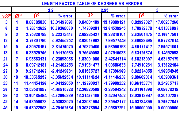
giving ERROR TABLE 1 for 3 different lengths of OA below:
|
|---|
|
|---|
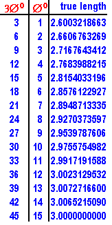
TRUE LENGTH TABLE 2: (for length OA)
|
|---|
|
|
Let 3Æ = ÐDOA and Æ = 3Æ/3 = ÐDOA/3 = ÐDAO
|
|---|
|
|
|
|---|
|
|
OM = ODcos3Æ and DM = ODsin3Æ
|
|
|
|---|
|
|
KC = FK*tan(3Æ/2) = OK*tan(3Æ/2)
|
|
|
|---|
|
|
OD = OC = OK + KC = OK + OK*tan(3Æ/2) = OK[1 + tan(3Æ/2)]
|
|---|
|
|
|
|---|
|
|
MA = DM/tanÆ = ODsin3Æ/tanÆ
|
|
|
|---|
|
|
OA = OM + MA = 0.6339746[1 + tan(3Æ/2)](cos3Æ + sin3Æ/tanÆ)
|
|
|
|---|
|
|
giving TRUE LENGTH TABLE 2 for OA, for every degree, below:
|
|---|
|
|---|
|
|---|
|
|---|
|
|---|
|
|---|