|
|
Xform > Modify >
Proportional mod

|
Reshaping Regions of Curves and Surfaces
|
|
|
|
|
Transforms a specified region on a curve or a surface without the transformation being applied to, or affecting, any area outside of this region.
For example, you can create controlled contortions to a surface representing recesses.
How to Use
|
|
|
-
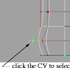
1
-
Select Proportional mod-
 from the
Xform > Modify cascading menu, or double-click its icon. The Pmod Control window appears (see page 197) and the system prompts: from the
Xform > Modify cascading menu, or double-click its icon. The Pmod Control window appears (see page 197) and the system prompts:
-
Select the primary CV.
|
|
|
-
2
-
Click a CV on the curve or the surface in the center of the region that you want to modify. A locator appears to identify the primary CV. (See the example on the left.)
-
3
-
The system prompts:
-
Enter MOVE amounts (x,y,z) (ABS):
-
Either type the move coordinates at the keyboard, or drag
the CV using the mouse. The object changes shape
according to how you move the CV.
-
4
-
Undo your changes at any time (while the CV is still selected), by clicking on the Revert button at the bottom of the control window.
|
|
|
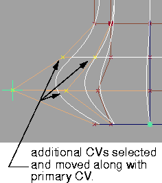
-
5
-
Determine how many additional CVs (preceding and following the primary CV in both the U and V directions) should be included to define the surface region affected by the modification.
-
Use the Preceding U/V and Succeeding U/V sliders in the
Pmod Control window to set these values. (In the example
on the left, we set Preceding# U = 1 and Preceding# V = 1)
-
The corresponding CVs are highlighted to show that they
have been selected and will be affected by further
modifications.
Proportional Modifications Options
Select Xform > Modify > Proportional mod- to display the Proportional Modification Options
window.
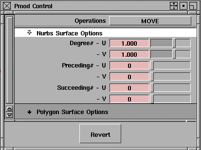
Operations
The type of modification performed depends on the current Operations option setting.
|
|
See:
Moving Objects on page 176,
Rotating Objects on page 180,
and
Changing the Dimensions
of Objects on page 185.
|
Move, Rotate
, and Nonp-Scale
-
- Operate in the same way as the standard Xform > Move, Xform > Rotate and Xform > Nonp scale functions. You can perform the modification with the mouse or with the keyboard, in absolute or relative addressing mode.
Smooth
-
- Performs an interpolation based on the current Degree # values for averaging the CVs in the region of effect.
-
- No interaction beyond selecting the primary CV and the region of effect is required when performing smoothing.
NURBS Surface Options
Degree #
-
- The Degree #
parameters specify the degree of effect in the U and V parametric directions. The range for these fields is from -5.00
to 5.00.
-
- As the transformation is applied, the amount by which the preceding and succeeding CVs are affected in relation to the primary CV is determined by the current degree value and the distance of each CV from its neighbor. A degree of 0 applies the transformation equally over the affected region.
-
- If this value is positive, the effect of the transformation is decreased for CVs that are further away from the primary CV-the greater the degree, the greater this dampening effect. The greater the number of CVs between the primary CV and the boundary of the defined region, the less of an effect the transformation has on each individual CV.
-
- If the degree is negative, the effect of the transformation is increased for CVs that are further away from the primary CV. The greater the number of CVs between the primary CV and the boundary of the defined region, the greater the effect of the transformation is on each individual CV.
Preceding #
-
- Use these fields to specify the number of CVs preceding the primary CV that you want to include in the region definition along the U and V parametric directions.
-
- The range of preceding CVs that can be affected by the operation ranges from 0 (the default) to N, where N is the maximum possible number of CVs in the given direction for the particular object. Hence, to select all CVs in a particular direction, simply drag the slider all the way to the right.
Succeeding #
-
- Use these fields to specify the number of CVs succeeding the primary CV that you want to include in the region definition along the U and V parametric directions.
-
- The range of succeeding CVs that can be affected by the operation ranges from 0 (the default) to N, where N is the maximum possible number of CVs in the given direction for the particular object. Hence, to select all CVs in a particular direction, simply drag the slider all the way to the right.
>
|
Note:
|
For a curve, only the U direction is used.
|
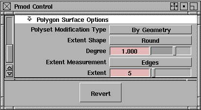
Polygon Surface Options
If you click on the Polygonal Surface Options title, the following set of options appears:
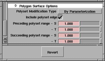
Polyset Modification Type
-
- Choose By Parameterization to modify the polyset based on texture coordinate parameterization, or By Geometry to modify it based on topology.
|
|
This option only appears
when Polyset Modification
Type is set to By
Parameterization.
|
Include polyset edge
-
- This toggle specifies whether polyset vertices that exactly equal the endpoints of the range specified by the Preceding
and Succeeding polyset range
options should be included in the proportional modification.
|
|
The default values for these
settings cause the entire
surface to be proportionally
modified.
These options only appear
when Polyset Modification
Type is set to By
Parameterization.
|
Preceding/Succeeding polyset range
-
- These slider values represent the range of polyset vertices that should be included in a proportional modification. The amount of modification applied to an individual polyset vertex depends on its S and T (also known as texture) coordinate values.
-
- On most polygonal surfaces, these values form a two-dimensional parameterization of the surface.
-
- The Preceding slider indicates what percentage of vertices with coordinates (either S or T) less than that of the target vertex should be proportionally modified.
-
- The Succeeding slider indicates what percentage of vertices with coordinates (either S or T) greater than that of the target vertex should be proportionally modified.
|
|
These four options only
appear when Polyset
Modification Type is set to By
Geometry.
|
Extent Shape
-
- Choose Sharp for a sharp drop-off, or Round for a smoother drop-off.
Degree
-
- Specify the degree of change as a function of the distance from the primary vertex. This option behaves the same as Degree# for NURBS geometry (see page 197).
Extent Measurement
-
- Choose either Edges or Polygons as the unit of measure for the Extent (see below).
Extent
-
- Specify how many units (i.e. edges or polygons - see above) from the primary vertex will be affected by the modification. If set to 0, only the primary vertex is modified. The default is 5.
Revert button
This button, located at the bottom of the control window, allows you to undo all your modifications since the currently active CVs were selected.
Notes
- If using Proportional mod
on faces, only the outline of the face or any one hole can be modified at a time. Additionally, remember that a face must be co-planar at all times.
|
|
For information on faces, see
the
NURBS Modeling
manual.
|
- Do not use Proportional mod
to effect a change on a face that would result in the face no longer being co-planar.
- This function only affects the location of CVs, and not the transformation matrix of the surface at the node above the geometry.
|


