|
Xform > Move 
|
Moving Objects | ||||
|
| |||||
PurposeLets you move any pickable item, including CVs and edit points. | |||||
|
See Using Absolute and Relative Addressing Modes on page 12 for information. |
By selecting from either absolute or relative addressing modes, geometry can be moved to absolute world space coordinates or relative to its current location. How to Use
Moving a Curve-on-Surface ElementA curve-on-surface element is a curve that has been plotted directly onto a surface in UV parameter space rather than being plotted in world space, or one that has been projected onto a surface as a result of a project, project normal, geometry mapping or intersect function. Curve-on-surface elements are typically used in trimming operations, and can be selected using Pick > Object types > Curve on surf. When you select a curve-on-surface element, you can move it anywhere on the surface (or entirely off the surface) with Xform > Move. Since a curve-on-surface element is mapped only to the UV parameter space of a surface, once the curve or any portion of the curve is moved off the surface, that portion is no longer displayed. If a curve-on-surface element is present on a surface, the system automatically assumes that this surface has been set up for a trimming operation. Therefore, the SBD window displays the surface as a target surface, as in the following DAG node structure: | ||||
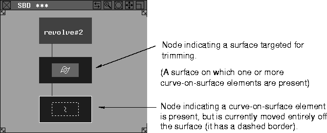
| |||||
To move a curve-on-surface element back onto the surface where it is visually mapped in UV parameter space:
Similarly, if an edit point on a curve-on-surface element is moved off the surface, the edit point and curve spans affected by that edit point are no longer displayed. To select the edit point that has been moved off the surface:
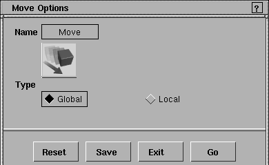
Move Options
Select Xform > Move-
TypeGlobal
Local
The default local axes for an object are the same as the global axes. You can change the local axes of an object using Xform > Local > Set local axes. >
Important Note on Construction HistoryIf the object being transformed is a result of an operation that uses construction history (such as Surfaces > Revolve), the integrity of the construction history cannot be maintained. A confirmation box is displayed asking if you wish to continue even though the construction history will be removed:
For more information on construction history, see the Nurbs Modeling book. | |||||
| Copyright © 1998, Alias|Wavefront, a division of Silicon Graphics Limited. All rights reserved. | Please send questions or comments regarding the documentation to: [email protected] |
 or
or  key.
key.
 to display the Move Options box.