Silberring Engineering Ltd.

Fire Protection of Steel Structures

Isometric Outline of a Protected Room


Some criteria for the walls surrounding the protected room have been already described in the previous sections. Additional particular information is shown in Fig. 2 and described below. These walls are composed of the following layers, listed below from inside to outside:

  • A steel box (14) with essentially vertical and reasonably tight walls.
  • A thermal shield composed of at least one row of tightly spaced risers (15Y), normally filled by water at ambient temperature. In case of a fire outside the protected room, water (possibly with some fraction of steam) flows upwards through the risers.
  • A barrier (16) made of appropriate solid materials according to the valid rules.
  • All above barriers must incorporate a system of locks, allowing the movements of persons and materials across them at various scenarios of operation or of fire without impair the essential objectives of the protected room.

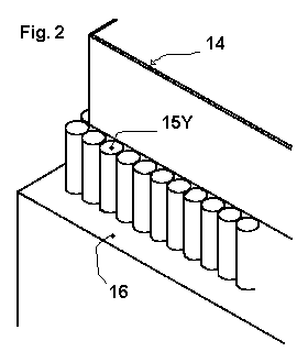
The system of the risers on the perimeter and, if any, inside of the protected room is connected to the remaining parts of the cooling system in a similar manner as already described for the Fig. 1. In particular, the risers (15Y) are connected to the same distributor and collector at the respective lower and upper end of the downcomer (5) as the risers (4) shown in Fig. 1. Both risers and downcomers on the perimeter and, if any, inside of the protected room can be considered as active structural elements of the building since they are protected by solid barriers as requested by rules.


Abstract
Inspiration
The Problem
The Outline of a Solution
The Main Cooling System and its Essential Elements

A Protected Room and its External Shield
The Fluid Pressure
Headers and Downcomers
Natural or Assisted Circulation

Isometric Outline of the Main Structure Cooling System
Some General Conditions
References
Home | About Us | Contact Us


Hosted by www.Geocities.ws

1