Silberring Engineering Ltd.

Fire Protection of Steel Structures

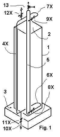
Isometric Outline of the Main Structure Cooling System


The Main Structure Cooling System is described below using an example and Fig. 1. The latter shows an isometric view of an outline of a high-rise building with four vertical walls [only their contours (1) are shown] that encompass a square horizontal section (2). The building is erected on a foundation (3). Vertical steel tubes are incorporated on the total height of the façades of all said walls; one only of them (4X) is shown in the Fig. 1. They are filled with water and act as risers in case of fire. Their external parts are insulated to prevent freezing of water stored inside.

A single downcomer (5) is selected for this example and placed in the center of the building's horizontal section. Its bottom and top parts serve respectively as distributor and collector of water (that may contain some steam at the top) to and from the tubes (4X) and may be enlarged for this purpose, as far as necessary. The tubes (6X) and (7X) connect the distributor to the bottom of every riser (4X) and the top of the latter to the collector. Appropriate valves (8X) and (9X) allow isolating any riser that became leaky for whatever reason. Tubes (10X) with drain valves (11X) allow to drain every isolated riser, whereas safety valves (12X) prevent an excessive rise of pressure in such riser. The common control valve (13) keeps the pressure in the system within the selected limits, either by relieving some steam or inert gas from the system or by introducing some of the latter into the system.


An internal kernel of the building (not shown in the Fig. 1) is selected as a previously mentioned, in this example single, protected room. Its square horizontal section is placed concentrically within the corresponding section of the external walls. This protected room runs across all stories of the building from its bottom to the top. Inside are placed all structures that cannot be easily cooled by individual internal channels as well as structures that must be protected by solid barriers in order to comply with any related rules. The central downcomer (5) is also placed within the protected room. Conversely, any easy igniting or burning materials shall be kept outside the protected room.


Abstract
Inspiration
The Problem
The Outline of a Solution
The Main Cooling System and its Essential Elements

A Protected Room and its External Shield
The Fluid Pressure
Headers and Downcomers
Natural or Assisted Circulation

Isometric Outline of a Protected Room
Some General Conditions
References
Home | About Us | Contact Us

Hosted by www.Geocities.ws

1