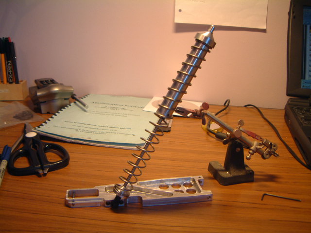
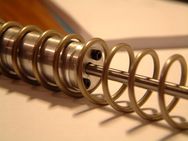
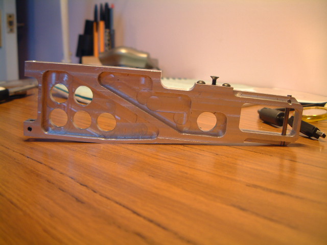
I want the suspension on this vehicle to be mind blowing. Real Class-1 desert racers have upwards of 2 feet of wheel travel all round, and often have 3 shock units per wheel. If my car is going to be about 1:6 scale, I need about 4" of travel. Working through some dimensions by eye and using CAD, I have come up with suspension arms 225mm long, using some industrial springs 205mm long unloaded. I can get over 4" travel out of this if necessary. The arms will be machined 1/4" alu, or possibly pocketed-out 10mm alu if I can get hold of the material and a milling machine which can handle work of that size. One of the big differences between a real desert buggy and the 1:10 and 1:8 models is that their suspension arms hang down a long way from horizontal, giving extra up-travel. On an RC model you will most likely see the arms pretty much level with the horizontal. My car is not going to be of the 'slammed' generation. It will be jacked up high, a bit of body roll is not going to kill anyone. With the laid down engines it should not roll too badly.
The springs will run over an air damper, which will have a Teflon piston in it. The air dampers' pistons have one-way valves which double the amount of damping they provide on the up-stroke. This will help to absorb big hits. There will also be separate oil damper units which will run next to (rather than the conventional inside) the springs. The oil dampers have less travel than the springs and air dampers so will be angled-in to give little damping at the down-travel limit, but much more when the suspension compresses. If I get it to work out I could upgrade these to long-travel magnetodynamic dampers in the future. With the proper springs and dampers, it will not be necessary to have more than one of each per wheel. The recent crop of fast monster trucks with 8 shocks only have them, in my opinion, because they use shocks which are designed for smaller, lighter work.
Below is a graphical simulation of the damper performance of this twin-damper system. It is the result of a numerical calculation taking into account shock geometry for both damper units, with separate damping coefficients. This model uses coefficients which express damper force as linear with damper compression speed. Maybe a square relationship would be slightly more accurate. The calculations would then be quite slow on my computer though...
|