|
Texture Placement Window
|
|
|
|
| |
|
The Texture Placement
window is sometimes
referred to as the Texture
Space Editor.
|
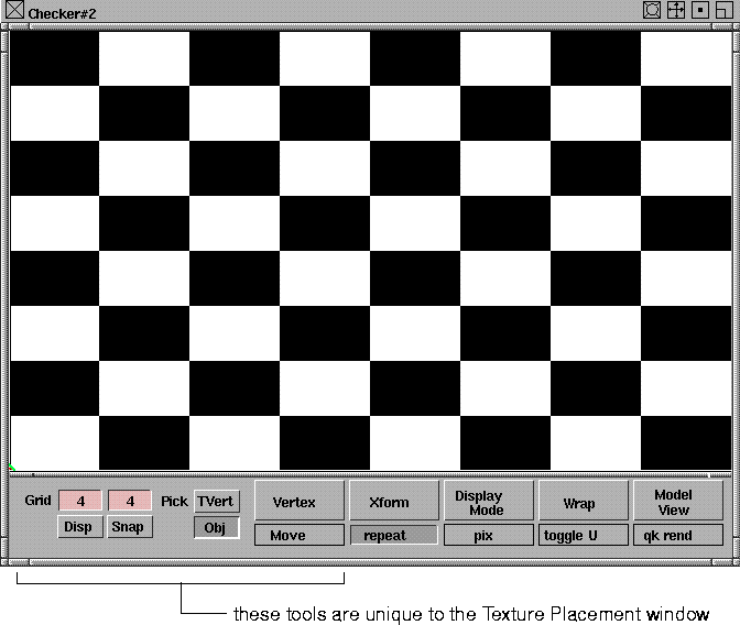
The Texture Placement window displays a texture that is mapped to a surface, and allows you to position the texture interactively. The two dimensions of this window (S and T) represent the two parametric dimensions of the active surface (U and V). A texture mapped to the active surface will therefore be displayed in the Texture Placement window relative to the surface. The buttons at the bottom of the Texture Placement window allow you to edit the position and orientation of the texture relative to the surface.
To open the Texture Placement window:
-
1
-
Select the texture swatch in the Multi-lister.
|
|

|
-
2
-
Click the 2D mapping icon in the texture swatch.
|
|
|
The title bar contains standard dolly and track icons, and full/half/resize, minimize, and close icons. The buttons and menus located along the bottom of the window let you interactively edit all Surface Placement and Label Mapping parameters. There are also some additional tools along the bottom of the window that are unique to the Texture Placement window.
Grid Buttons
The Grid buttons allow you to display a grid in the window, specify the size of the grid, and enable snapping of texture vertices to the grid.
Disp
-
- Displays a light grey grid in the window. The numeric field above the Disp button controls the number of vertical grid lines (representing U in parametric space), and the numeric field above the Snap button controls the number of horizontal lines (representing V in parametric space). Click in either of these fields to change the number of grid lines.
Snap
-
- Enables snapping of texture vertices to the nearest grid location when you perform texture vertex transformations.
Pick Buttons
The Pick buttons, Obj (Object) and TVert (Texture Vertices) allow to you to select geometry or vertices in the modeling window, and load them into the Texture Placement window. Picking geometry or vertices in the modeling window is similar to using the Pick > CV tool:
|
Mouse Button
|
Selection Description
|
|---|
| left
| toggles selection
|
| middle
| deselects all vertices or geometry
|
| right
| deselects vertex or geometry
|
The Obj and TVert buttons are mutually exclusive; only one can be active at a time.
Obj
-
- Allows you to select polygonal geometry in the modeling window and load it into the Texture Placement window. You can modify geometry loaded into the Texture Placement window using the Xform tools.
-
- If any polysets, components, or polygons are selected when you first open the Texture Placement window, all polysets or fully selected polygons are loaded (if all of their vertices are selected) into the Texture Placement window. This geometry is displayed as two-dimensional parametric space geometry. At any point after you open the window, you can change the loaded geometry by clicking the Obj button and selecting the geometry in the modeling window.
-
- When the Obj button is selected, you can select polygonal geometry at the vertex level by clicking and dragging in the modeling windows (like using the Pick > CV tool). Only polygons that have all of their component vertices selected will be loaded into the Texture Placement window.
-
- If you have selected polygonal geometry prior to opening the Texture Placement window, the Obj button is selected by default, and all Texture Placement window tools are enabled. If, however, you do not have polygonal geometry selected prior to opening the Texture Placement window, the Obj button will not be selected, and all Texture Placement window tools (except for the Obj button) are disabled. Selecting polygonal geometry as above will enable the tools.
|
|
A continuous tool is one that
remains active after you
have selected it and used it
to perform an action (for
example, Xform > Move).
|
-
- If you select another continuous tool (such as Xform > Move) while using the Texture Placement window, all geometry is unloaded and the Obj button is deselected. If you select the Obj button again, you can reload all active geometry. This also exits the continuous tool.
TVert
-
- Allows you to select polyset vertices in the modeling window. These vertices correspond to the vertices displayed in the Texture Placement window. You can modify selected vertices using the Vertex tools in the Texture Placement window.
|
|
|
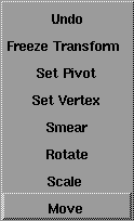
Vertex Menu
The Vertex tools let you interactively transform selected polyset vertices.
There are several methods you can use to select vertices.
- You can select an individual vertex in the Texture Placement window by clicking on it. You can select multiple vertices in the Texture Placement window by holding the Shift key and click-dragging a box around the vertices.
- You can select individual or multiple vertices in the modeling window by clicking the TVert button and then clicking on (or click-dragging a box around) the vertices in the modeling window.
- You can select all vertices associated with a polygon in the Texture Placement window by holding the Alt key and clicking in the middle of the polygon. This includes all vertices that are shared with other polygons.
- You can select all vertices associated with a polygon in the Texture Placement window by holding the Alt and Ctrl keys and clicking in the middle of the polygon. This does not include vertices that are shared with other polygons.
- You can select and transform a vertex without affecting any polygons that share that vertex. First, select the vertex using any of the methods described above, and then press the -> (right arrow) key. A white diamond-shaped marker is displayed in one of the polygons that shares this vertex. Press the -> key again until the marker is in the polygon that you want to transform the vertex for. Transform the vertex using any of the Vertex tools. Press the <- (left arrow) key to remove the marker.
Move
-
- Lets you move selected vertices in the Texture Placement window by clicking and dragging in the window.
|
Mouse Button
|
Move Direction
|
|---|
| left
| freeform
|
| middle
| equal in S and T directions
|
| right
| along the S or T axis
|
|
|
To move the pivot point, see
Set Pivot on page 142.
|
Rotate
-
- Lets you rotate selected vertices about the current pivot point in the Texture Placement window by clicking and dragging in the window. The pivot point is indicated by a small green circle in the Texture Placement window, and is in the bottom left corner of the window by default.
|
Mouse Button
|
Move Direction
|
|---|
| left
| clockwise
|
| right
| counter-clockwise
|
|
|
To move the pivot point, see
Set Pivot on page 142.
|
Scale
-
- Lets you scale selected vertices about the current pivot point in the Texture Placement window by clicking and dragging in the window. The pivot point is indicated by a small green circle in the Texture Placement window, and is in the bottom left corner of the window by default.
|
Mouse Button or Direction
|
Scale Type or Direction
|
|---|
| left button
| non-proportional scale
|
| middle button
| proportional scale
|
| right button
| along the S or T axis
|
| right or up direction
| scale up (larger)
|
| left or down direction
| scale down (smaller)
|
Smear
-
- Lets you smear selected vertices in the Texture Placement window by clicking and dragging in the window. Vertices closest to the mouse pointer are moved more than vertices further away from the mouse pointer.
|
|
You can also select the Set
Vertex function by moving
the mouse pointer over the
Texture Placement window
and pressing the S key.
|
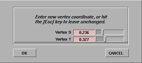
Set Vertex
-
- Lets you enter numeric S and T values to re-position the selected vertex. When you select Set Vertex, the following dialog box is displayed.
Set Pivot
-
- Lets you move the pivot point (used during Scale and Rotate operations) by clicking and dragging in the Texture Placement window. The pivot point is indicated by a small green circle in the Texture Placement window, and is in the bottom left corner of the window by default.
-
- To center the pivot point within the selected vertices, move the mouse pointer over the Texture Placement window and press the C key.
Freeze Transform
-
- Applies any Translate, Coverage, Rotate, Offset, or Repeat values (set using either the Xform tools, or the actual parameters in the texture's Control Window) to all vertices loaded in the Texture Placement window.
-
- The texture coordinate that results from the transformation is calculated and then assigned to the appropriate texture vertices in the Texture Placement window. A system prompt also asks whether you want to reset the texture transform values before you confirm the operation. If you decide to reset, then the transformation values are set to their defaults.
-
- The Freeze Transform tool is very useful when preparing texture coordinate data for export to systems that do not support advanced placement options such as Translate, Coverage, Rotate, Offset, and Repeat.
Undo
-
- Undoes the last vertex transformation you performed. You can also select the Undo function by moving the mouse pointer over the Texture Placement window and press the U key.
Vertex Flipping Hot Keys
Two other vertex tools are available only by using hot keys in the Texture Placement window.
H (Horizontal Flipping)
-
- Scales the S value of the selected vertices by a factor of -1 around the center of the selected vertices (no matter where the pivot point is). This flips the vertices horizontally.
V (Vertical Flipping)
-
- Scales the T value of the selected vertices by a factor of -1 around the center of the selected vertices (no matter where the pivot point is). This flips the vertices vertically.
|
|
|
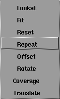
Xform Menu
The Xform tools let you transform the texture relative to the active surface it is mapped to. Any transformations you make using these tools are automatically updated in the texture's Surface Placement and Label Mapping parameters. The origin of the texture is in the lower left corner of the window. The U parametric direction is horizontal, and the V parametric direction is vertical.
Translate
-
- Lets you move the texture on the surface by clicking and dragging in the Texture Placement window. This tool controls the texture's Utranslate and Vtranslate values.
Coverage
-
- Lets you reduce the coverage of the texture on the surface by clicking and dragging in the Texture Placement window. This tool controls the texture's Ucoverage and Vcoverage values.
Rotate
-
- Lets you rotate the texture on the surface by clicking and dragging in the Texture Placement window. The texture is not actually rotated in the Texture Placement window. Instead, a white border representing the edges of the surface is rotated. This tool controls the texture's Rotate value.
Offset
-
- Lets you offset the texture's position on the surface by clicking and dragging in the Texture Placement window. This tool controls the texture's Uoffset and Voffset values.
Repeat
-
- Lets you change the number of times the texture is repeated within the coverage area by clicking and dragging in the Texture Placement window. This tool controls the texture's Urepeat and Vrepeat values.
Reset
-
- Undoes the last transformation you performed.
Fit
-
- Automatically fits the texture to the surface.
Lookat
-
- Dollies the display in the Texture Placement window so that the placement object (representing the surface) fills as much of the window as possible.
|
|
|
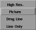
Display Mode Menu
The Display Mode tools let you change the way the surface and texture are displayed in the Texture Placement window. The default display mode is Picture.
Line Only
-
- Displays the surface as a white outline, the texture as a red outline, and the grid as blue lines.
Drag Line
-
- Displays the texture as a color image against the shader color, unless you are using an Xform function. During Xform operations, the display changes to Line Only mode. When the Xform operation is completed and the mouse button is released, the texture is displayed as a color image again.
Picture
-
- Displays the texture as a color image at all times.
High Res.
-
- Displays the texture as a high resolution color image at all times. High Res. mode may be slower than other display modes.
|
|
|
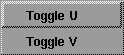
Wrap Menu
The Wrap tools let you repeat the texture pattern outside of its coverage area.
Toggle V
-
- Wraps the texture outside of its coverage area in the V parametric direction. This tool controls the texture's Vwrap setting.
Toggle U
-
- Wraps the texture outside of its coverage area in the U parametric direction. This tool controls the texture's Uwrap setting.
|
|
|
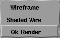
Model View Menu
The Model View tools let you change the type of view in the modeling window.
|
|
See Quick Render on
page 362.
|
Qk Render
-
- Quick renders all surfaces to which the texture is mapped.
|
|
See 3D Mapping on page 132.
|
Shaded Wire
-
- Displays the texture on the wire frame of the active surface if the texture is mapped to that surface. This tool activates 3D mapping.
Wireframe
-
- Displays the active surface in normal wire frame view. This tool toggles the modeling windows out of Shaded Wire mode.
|


