|
ObjectDisplay > Diagnostic Shading |
Diagnostic Shading | ||
|
| |||
This tool is only available to users who do not have access to the Control Panel (see Using the Direct Modeling Control Panel in the NURBS Modeling book). Overview | |||
|
|
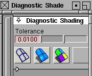
These options let you work with shaded geometry instead of wireframes so that you can see and evaluate your surfaces. There are different shading modes available that provide different diagnostic information about your surfaces. These shading modes use highly optimized, high performance routines to allow you to interactively work in the shaded mode. Diagnostic Shading is much faster than the Shade tool (see Toggling between Shaded and Wireframe Views on page 306) For example, with the Transparency option, you can visualize the model as you tumble the camera-you can see CVs and continue to pull and tweek them while any of the shading mode is turned on. By default, Diagnostic Shading uses a point light located at the eye position of the camera. You cannot see or pick this light as an object, but you can change its parameters through the Diagnostic Shading options. How ToTo shade objects:
To control the speed and quality of the shading:
To change the options for a shading mode. | ||
|
|
| ||
|
|
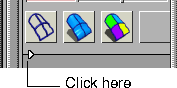
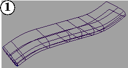
The illustration at left shows the different shading options. Refer to the following sections for information on each of these modes, and the options available for them.
| ||
|
|
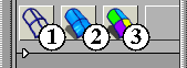
1. No shadingThe wireframe model appears with no shading. No settings are available with this shading mode.
| ||
|
|
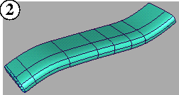
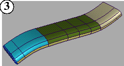
2 & 3. Single color & Random colorSingle color mode shades all the picked surfaces with a single colour which you can set. The adjacent random color button shades the surface with random colors. As a result the adjacent surfaces show up in different color, making it easier to see the patch structure. Control the type of shading with the following options: | ||
|
|
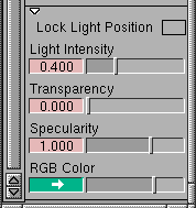
Lock Light Position
Light Intensity
Transparency
| ||
|
|
Specularity
RGB Color
Color Saturation
Using other lights | ||
|
For more information on lights, see Lights in the Rendering in Alias book. |
Instead of the default Diagnostic Shading light, you may choose to use up to eight regular lights to illuminate your model while in Diagnostic Shading mode. These lights can be edited using the Multi-Lister in the usual fashion. The following types of lights can be used:
|
| Copyright © 1998, Alias|Wavefront, a division of Silicon Graphics Limited. All rights reserved. | Please send questions or comments regarding the documentation to: [email protected] |