 |
 |
|
|
|
|
|
|
|
| <<Home | Lab 5 | |||
|
Different responses of a filter
Exercise 1 Determine and sketch the impulse response, step response, magnitude response and phase response for the following filter for b=1 and b=-1.
x[n] y[n]
+
y[n] y[n] = x[n] + bx[n-2] +x[n-4]
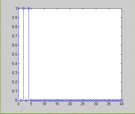
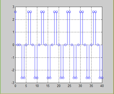
Solution %impulse response num = [1 0 1 0 1] den = [1 0 0 0 0] N = 41; x = [1 zeros(1, N-1)]; y= filter(num,den,x); k=0:1:N-1; stem(k,y) %step response figure xx = [ones(1,N)]; yy= filter(num,den,xx); kk=0:1:N-1; stem(kk,yy) %magnitude response w= -pi:pi/255:pi; h=freqz(num,den,w); h1=abs(h); h2=h1/(max(h1)); h3=20*log10(h2); figure plot(w,h3);
%this is for the Phase Response h4=angle(h); %since phase cannot be in DB so no h2 and h3figure plot(w,h4) Result Impulse response
Step response
Magnitude response
Phase response
Different responses of FIR filter
Exercise 2 An FIR filter is described by the difference equation y[n] = x[n] - x[n-10] (a) Compute and sketch its magnitude and phase response. (b) Determine its response to the input x[n] = cos[л/10]n + 3sin(л n/3+л/10) Solution num= [1 0 0 0 0 0 0 0 0 0 -1] den = [1] %magnitude response w= -pi:pi/255:pi; h=freqz(num,den,w); h1=abs(h); figure plot(w,h1); %this is for the Phase Response h4=angle(h); %since phase cannot be in DB so no h2 and h3 figure plot(w,h4)
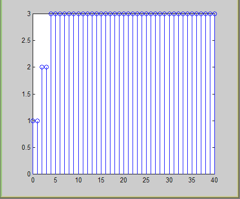
%PART B N=41; n=0:1:N-1; x = cos ( pi / 10 ) *n + 3 * sin (pi/3*n + pi/10); y = filter(num,den,x); k=0:1:N-1; stem(k,y) Result Magnitude response
Phase response
(b) Response to the input x[n]
Magnitude response
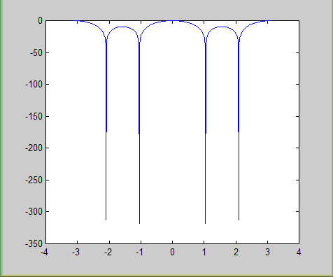
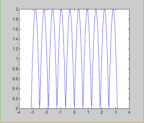
Exercise 3a Sketch magnitude response of the following filters. H(z) = {b0(1-2z-1cosw0+z-2)}/(1-2rz-1cosw0 +r 2z -2) where r = 0.95 and w0 = л/4 Solution b=0.954; r=0.95; w0 = pi/4 num= [b*1 -2*b*cos(w0) +b] den= [1 -2*r*cos(w0) + r*r] %magnitude response w= -pi:pi/255:pi; h=freqz(num,den,w); h1=abs(h); plot(w,h1); grid Result
Magnitude response
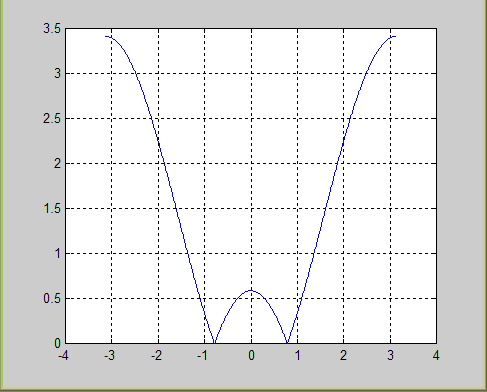
Exercise 3b Sketch magnitude response of the following filter. H(z) ={1/(M+1)}*b0(1-z-L(M+1))/(1-z-L) where M=10 and L=3 Solution num= [1 zeros(1,32) -1] den= [11 0 0 -11] %magnitude response w= -pi:pi/255:pi; h=freqz(num,den,w); h1=abs(h); figure plot(w,h1); grid Result
Impulse response, magnitude response and phase response
Exercise 4a Consider the following filter.
x[n]
-2cosw0 (a) Determine the input-output relation and sketch impulse response.
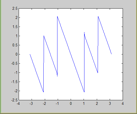
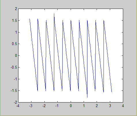
Solution num= [1 -2*cos(pi/2) 1] den= [1] %magnitude response w= -pi:pi/255:pi; h=freqz(num,den,w); h1=abs(h); figure plot(w,h1); grid on %this is for the Phase Response h4=angle(h); %since phase cannot be in DB so no h2 and h3 figure plot(w,h4) Result
Impulse response, magnitude response and phase response
Exercise 4b Consider the following filter.
+ y[n]
-2cosw0
(b) Sketch magnitude and phase response for w0 = л/4 and л/2 radians/second.
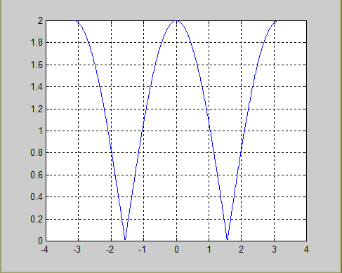
Solution % for w0 = л/4 num= [1 -2*cos(pi/4) 1] den= [1] %magnitude response w= -pi:pi/255:pi; h=freqz(num,den,w); h1=abs(h); plot(w,h1); grid % for w0 = л/2 num= [1 -2*cos(pi/2) 1] den= [1] %magnitude response w= -pi:pi/255:pi; h=freqz(num,den,w); h1=abs(h); figure plot(w,h1); grid Result for w0 = л/4
for w0 = л/2
Impulse response, magnitude response and phase response
Exercise 4c
Consider the following filter.
+ y[n]
-2cosw0
(c) When w0=л/2 determine the output y[n] when x[n]=3cos(л n/3 +3л) Solution num= [1 -2*cos(pi/2) 1] den= [1] N=41; n=0:1:N-1; x = 3 * cos ( pi / 3 *n + pi / 6 ); y = filter(num,den,x); k=0:1:N-1; stem(k,y) Result
DSP Lab 1 DSP Lab2 DSP Lab 3 DSP Lab4 DSP Lab 5 DSP Lab 6 DSP Lab7 DSP Lab8 DSP Lab9 DSP Lab10 Other material |
||||
| <<Home | ||||
|
||||||