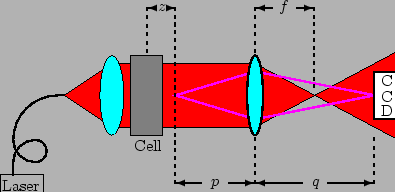
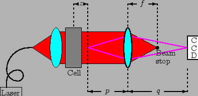
The systems are sketched in Figs. 4.10 and 4.11.
 |
 |
The measurements described in Chapters
7 and
8 cover the wavevector range
![]() about
about
![]() .
By using Eqs. (4.1) and
(4.4), we obtain
.
By using Eqs. (4.1) and
(4.4), we obtain
![]() and
and
![]() .
A
.
A
![]() beam diameter, obtained with
lenses with
beam diameter, obtained with
lenses with
![]() diameter, as shown in
Fig. 4.2, is enough to ensure
that the intensity is constant over the length
diameter, as shown in
Fig. 4.2, is enough to ensure
that the intensity is constant over the length ![]() . For the
measurements described in Chapters 7 and
8, we used larger lenses with
. For the
measurements described in Chapters 7 and
8, we used larger lenses with
![]() diameter, with a larger beam diameter, in order to
ensure a better uniformity, and
diameter, with a larger beam diameter, in order to
ensure a better uniformity, and ![]() was increased acordingly.
was increased acordingly.
Following Eq. (4.3), we obtain the
magnification: ![]() . We used a 20X microscope objective and
numerical aperture of 0.45.
. We used a 20X microscope objective and
numerical aperture of 0.45.
The whole optical system for ENFS is shown in Fig. 4.2.
For ONFS, we insert a beam stop through a hole inside the lens mount. The beam stop and its adjustable mount is shown in Fig. 4.7.