


Next: The light source.
Up: The experimental system.
Previous: The experimental system.
Contents
The optical system is mainly built using elements supplied by Newport.
The optical table is a VH3048 IsoStation. All the elements are mounted on
X26 rails, by using CN26 carriers.
A picture of the system is shown in Fig. 4.2.
Figure 4.2:
Picture of the optical system. From left to right, we can see
the adjustable mount that holds the fiber, the collimating lens, the cell,
the microscope objective and the CCD camera.
In the upper right corner there's the laser mount.
![\includegraphics[scale=0.82]{exper_sistema_ottico.ps}](img310.png) |
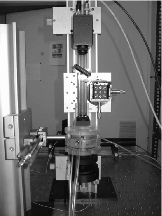
For the experiment descibed in Chapter 9,
the optical axis must be vertical. The X26 rails are held in vertical
position by mounting them on an X95 rail with suitable carriers: see
Fig. 4.3.
Figure 4.3:
A view of the optical system for
the experiment described in Chapter 9. All
the optical elements are alligned in vertical direction. From
the bottom, we see the optic fiber, held by an adjustable mount, the
collimating lens, the cell, held by the column on the left, the
focusing lens, the blade, the neutral filter, and the CCD camera.
 |
Next: The light source.
Up: The experimental system.
Previous: The experimental system.
Contents
2003-01-09