The objective must form an image of a given plane on the CCD
sensor. The magnification ![]() must be selected in order that the
required wavevector range
must be selected in order that the
required wavevector range
![]() is inside the
wavevector range the CCD sensor can measure: about
is inside the
wavevector range the CCD sensor can measure: about
![]() .
This means that:
.
This means that:
In our experiments, we used a 20X microscope objective for high
magnification factors, and an achromatic,
![]() focal length
doublet for magnification factor around
focal length
doublet for magnification factor around ![]() .
An achromatic doublet has also been tested for high magnification
factors, since we do not
require the high quality of a microscope objective, nor an extremely wide
numerical aperture. Experiments proved no different performances of
the doublet compared with the microscope objective, but it was more
difficult to obtain the required magnification.
.
An achromatic doublet has also been tested for high magnification
factors, since we do not
require the high quality of a microscope objective, nor an extremely wide
numerical aperture. Experiments proved no different performances of
the doublet compared with the microscope objective, but it was more
difficult to obtain the required magnification.
The objective lens must be placed so that it creates an image of a
given plane on the CCD sensor. For ONFS and ENFS, the plane must be at
a distance ![]() from the sample fulfilling
Eq. (3.60). The best choice is:
from the sample fulfilling
Eq. (3.60). The best choice is:
For ONFS, the transmitted beam, focused by the objective, is stopped
by an opaque or reflective element. In microscope objectives, the
focal plane is inside, between two groups of lenses: we insert the beam
stop through a hole.
We tried three kinds of beam stops: a thin wire, a reflective wedge and
an absorbing disc impressed by on a photographic film.
The wire has a diameter of
![]() ;
it si stretched in the focal plane
and is positioned by micrometric screws. It reflects the light
inside the objective, and this could, in principle, increase the stray light.
The photographic film we used are high contrast, black and white,
;
it si stretched in the focal plane
and is positioned by micrometric screws. It reflects the light
inside the objective, and this could, in principle, increase the stray light.
The photographic film we used are high contrast, black and white,
![]() photographic films. The beam stop is circular, but the
beam is not completely blocked, thus increasing the stray light.
The wedge was obtained by a steel blade; the edge was kept parallel to the
optic axis. The upper part, in the direction from which the light comes, was
cut at
photographic films. The beam stop is circular, but the
beam is not completely blocked, thus increasing the stray light.
The wedge was obtained by a steel blade; the edge was kept parallel to the
optic axis. The upper part, in the direction from which the light comes, was
cut at
![]() and polished, in order to obtain a surface that reflects
the main beam outside the
lens mount, through a second hole. A section of the objective lens is
shown in figure (4.6).
and polished, in order to obtain a surface that reflects
the main beam outside the
lens mount, through a second hole. A section of the objective lens is
shown in figure (4.6).
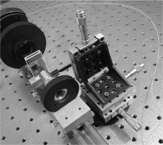 |
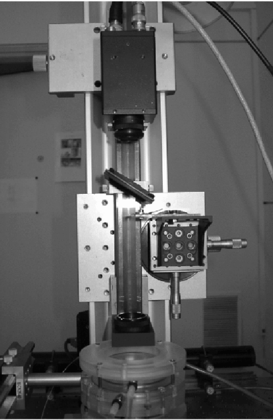
For SNFS, a blade must be placed in the plane where the transmitted beam is focused. The blade must be extremely sharp: a razor blade is required. We mount it on a system with three micrometric screws, in order to accurately position it in the space. A picture of the Schlieren system is shown in Fig. 4.8.
 |

