|
Select Edit > Duplicate
object- to display the
Duplicate Objects Options
window. to display the
Duplicate Objects Options
window.
|
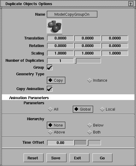
The Duplicate Objects options let you position, scale, or rotate objects as they are copied.
|
|
If you use default values for
all of these options, an exact
copy of the original is placed
at its exact location-you
will have to move the copy
to see the original.
|
Use the Translation,
Rotation, and Scaling options to specify offset values for the X-, Y-, and Z-axes. These offset values are applied to the copied geometry, and move it off of the original geometry. The values you specify in each field can be positive or negative floating-point values.
Parameters
Translation
-
- Offset values translate (move) the geometry as it is copied relative to the location of the original geometry.
-
- The default value for each axis is 0.0000 (no movement).
Rotation
-
- Rotation values are applied to the copied geometry.
-
- The default value for each axis is 0.0000 (no rotation).
|
|
Negative scale values reflect
the object around or through
its pivot point, and are
commonly used to create
mirror images.
|
Scaling
-
- Scaling values scale the copied geometry by the specified factors, relative to the current scale at the time it is copied.
-
- The default value for each axis is 1.0000 (no scaling).
|
|
If you specify multiple
copies, each copy is
translated, rotated, and/or
scaled relative to the
previous copy.
|
Number of Copies
-
- This is used to specify the number of copies you want to create. If more than one copy is specified, transformation and offsets are applied to each subsequent copy.
Group
-
- Specifies whether or not the copied geometry should be a child of the same parent as the original geometry from which it was copied. The default is ON.
-
- When Group is toggled OFF, all active geometry is deselected and the system prompts:
-
- Pick the item to be copied and placed in a new branch
Geometry Type
-
- These check boxes let you specify whether actual copies of the selected geometry are made, or whether the geometry is instanced. The default is Copy.
-
- For more information, see Using Instances on page 218.
>
|
Note:
|
When Geometry Type is set to Instance, the Group option is
set ON automatically.
|
Copy Animation
|
|
These parameters only apply
to animated objects.
|
Parameters
-
- Use these check boxes to copy channels for All, Global, or Local parameters. To find out how to turn animation parameter controls on or off, see Animation > Param control in the
Animating in Alias book.
Hierarchy
-
- Use these check boxes to specify which parts of a hierarchical animation are copied.
-
- None- Copies only the animation associated with the picked object.
-
- Above-Copies the animation from picked nodes and the nodes above them.
-
- Below-Copies the animation from the picked nodes and the nodes below them.
-
- Both-Copies all animation from the picked nodes, the nodes above them, and the nodes below them.
Time Offset
-
- This slider lets you change the start time of the animation of the object being copied. This setting is applied to all nodes of the chosen hierarchy, not just the picked node.
Animation Notes
- If the object being copied has timewarps applied to its channels, all the timewarps associated with each parameter are also copied. In this case, time offsets are achieved by adding a time shift warp, not by moving the animation curves' CVs.
- Time offsets are ignored for any expression that is copied.
Using Instances
When you use the Copy option with Edit > Duplicate object-, all active curves and/or surfaces are copied. Each copy can be independently altered, because it contains the complete set of data of the original object (and it takes up the same amount of memory as the original).
Duplicate objects;instances:definition;copying:advantages of creating instances instead>If you use the Instance option instead, you create instances, which are not actual copies of the selected geometry. Instanced geometry is always identical to the original geometry, although it is displayed on the screen according to the Duplicate Object options. For example:
- You can create numerous copies of the geometry with the parameter Number of Copies.
- You can change any particular instance with the factors you specify for Translation, Rotation, and Scaling.
- You can pick any one instance as an object independent of other instances.
The geometry of all instances remains the same. For example, if you move a CV on the original geometry, it affects the shape of all instances of that geometry.
Advantages to using instances
Using instances provides the following advantages:
- If you make a change to the original, all instanced copies automatically reflect the same change. This feature is especially valuable for animation.
- Since instances are not actual copies of the original geometry, they take up far less system memory. In large or complex model scenes, using instances can speed up refresh time, reduce the size of data files, and improve rendering times.
Limitations when using instances
- Instanced geometry does not display CVs or hull structure. The form of an instance can only be altered from the original geometry.
- Instances share the same shader as the original geometry and cannot be assigned independent shaders.
- Some functions, such as Insert, cannot be used on instanced items. In these cases, it is necessary to make a true copy of the instanced geometry that you want to manipulate and continue with the function.
-
To do this, copy the instance with the Geometry Type set to
Copy. This creates an uninstanced copy of the instance.
- Clusters and deformation frames can only be applied to the original geometry, and cannot be assigned to instances independently. To use clusters and deformations on copies, it is necessary to make a true copy of the geometry.
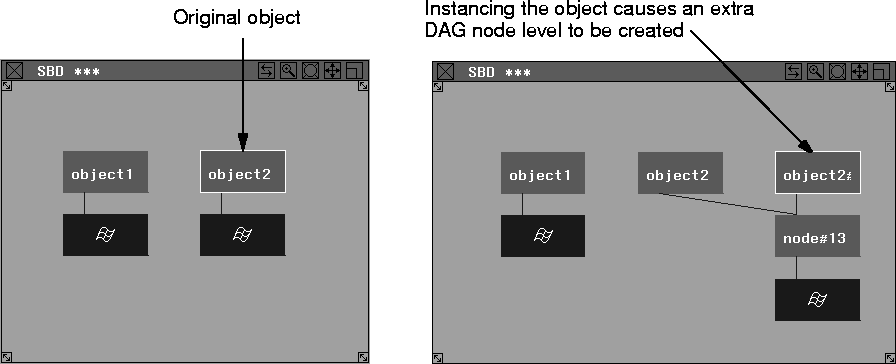
- There is always at least one non-instanced transformation node between the instance nodes and the actual geometry nodes.
- When you create an instance of an already instanced node, no new level is created.
DAG node representation of instances
When an instance is first created, an extra DAG node level is added in the SBD window, as shown in the following diagram. (The top DAG node is the transformation node and the lower DAG level is the geometry node.)
|