|
Project description
3.1 Sound Imaging Tool
3.2 Project objectives
3.3 Implementation
3.4 Activities and schedule
Chapter 3: Project
description
3.1 Sound Imaging Tool
In theater system or home surround system, there are some
tools being developed for professionals to setup and check the system for
correct imaging. The listening environment can creates distortions caused by
multi-paths of acoustic sound and other causes. These can cause imaging, or
sound localization errors, to the listener. One such product is called the LEDR
[4]� Listening Environment Diagnostic Recoding � tool. The LEDR is an objective
tool for testing and adjusting loudspeakers, and room acoustics that requires no
test instrumentation. If a stereo system corrupts or distorts one or more of the
LEDR paths, that system cannot be considered accurate.
The LEDR consists of a series of computer-generated
sounds that are intended to move in a predefined way between a pair of
loudspeakers. A sampled instrument music is electronically manipulated to move
through three different paths. The paths are Up, Over, and Lateral. The
differences between what these signals are designed to do, and what the test
system actually produce, represent a measure of the imaging accuracy of the
stereo speakers, electronics, and the room environment.
The first path - Up path. This path is generated first
in the left speaker, then in the right. The sound should begin at about eye
level and then travel as straight as possible up in the air about 6'.
The second path - Over path, also called the "Rainbow"
path. The sound begins at one speaker and travel in a smooth arc to the other
speaker, from left to right and then returning. The top of the rainbow should be
as high as the previous Up signal (about 6' above eye level).
The last path - Lateral, tests left-to-right stereo
imaging. This consists of four elements.
First, the sound moves from left to right, between the
acoustic centers of the speakers. Since a speaker's acoustic center may not be
its physical center, the first Lateral test is used to adjust your speakers
until the sound traverses a 60 degrees angle from the listener's point of view.
Second, the sound moves from beyond the right loudspeaker
to beyond the left (about 1' out from acoustic center).
The next two signals are the mirror image of the above;
Third, from right to left speaker; and Fourth, from beyond the left to beyond
the right.
The LEDR test can be use to grade the test system by how
straight, continuous, and symmetrical the paths are.
3.2 Project objectives
The project objective is to develop a tool for testing
and grading a four speakers home surround system � two front and two rear
speakers � by moving a sound laterally at fix positions around the listener.
Refer to figure 3.1. These will not only demonstrate the localization cues, but
also provide a simple tool for grading and improving the speaker locations /
settings, and to check the listening environment.
As an extended goal after achieving the main objective,
frequency notches may be introduces to simulate sound localization in the
vertical plane from the front center to the rear center.
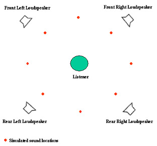
Figure 3.1:
Speaker�s layout and simulated sound locations
3.3 Implementation
Below are the implementation processes for realizing the
objective.
The DSP board in mind is the Speedy33. As only two
channels are available on each board, it is proposed to have two such DSP boards
to process the codes, and feed to the front and rear power amplifiers for
driving the four speakers. Refer to figure 3.2.
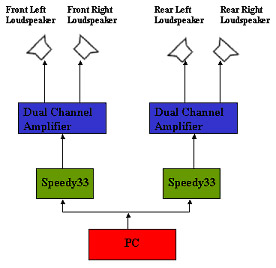
Figure 3.2:
Hardware block diagram
The two dual channels power amplifiers shall be
fabricated based on an off-the-shelve design.
Four 5-Watts loudspeakers shall be acquired.
A program using Matlab will be written to condition a
music sound wave file in magnitude, phase and frequency in each of the four
channels to simulate direction of the sound as in figure 3.1 above.
Labview shall be used to program the codes to the two
Speedy33 boards.
Extended goal:
After achieving the basic objective above, frequency
notches may be introduces to the codes to simulate the sound source in the
vertical plane.
3.4
Activities and schedule:
Month Task / Deliverables
May 07 Code writing and simulation.
Jun /Jul 07 Fabricate amplifiers and setup test
configuration.
Acquire
loudspeakers.
Test program.
Extended goal � localization in
median plane.
Preparation of FYP Final report.
Aug 07 Preparation of website.
Presentation material.
|