|
Lift
system of a hover craft is major a principle part ,
since whole pay load has to lift above the
gravitational force. For a lift system needs a powerful engine, a higher
r.p.m fan, casing around the fan for preventing escaping air.
Lift system should be designed such that it has to
continuously supply air below the hull & in to the skirt such that
it has to maintain constant air cushion. If the lift system is
worked out properly than amount of DRAG that existing in a hover
craft is too less. The amount of hovering height of a hovercraft is
completely depends on lift system (i.e. engine, propeller) .
Our lift system consists:-
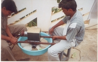
It was consists 150c.c Engine, Gear box, Propeller.
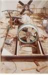
When we were started our project we gave a lot of importance to lift
system, such that first we have decided that propeller has to rotate in a
horizontal plane in vertical axis. Since we had only horizontal
shaft out put engine, this was made us very problematic. If the propeller
rotates in a horizontal plane than it will pushes air axially below the
hull & in to the skirt was our idea. To continue with this idea it
leads to us go for a GEAR BOX. A gear box acts as intermediate
between a engine and propeller. We have fabricated a SPIRAL BEVEL GEAR BOX
which will transmits power from engine output shaft to propeller in
horizontal plane.
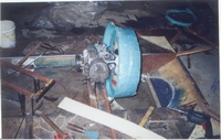
Problems from this arrangement:-
1)Initially when it was working we were satisfied with this arrangement
but problem arose with the engine that when the temperature of engine
exceeds 75 c, engine was comes to off due to high temperature generated.
This was because it has to drive gearbox & than propeller so that
temperature raises very rapidly.
2)Power loss from the gear box
3)Weight of the arrangement.
Because of the above problem we stopped our work for a period of 1 week
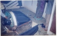
Finally we have decided to couple the
propeller to engine output shaft, such that it has to run in a vertical
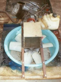
plane, horizontal axis. This arrangement was leads to fabricate a AIR BOX
. A airbox consists a propeller rotates in a vertical plane, draws air
horizontally turn it to 90˚ axially below the
surface of hull.
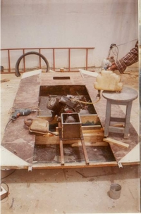
Fabrication of air box.
The walls of the air box were fabricated using hardboard (composite
material) and it was air sealed using putty and epoxy resin mix. The rest
of the portion was constructed using left over skirt material i.e., nylon
fabric with poly urethane coating.
Advantages of connecting the axial fan directly to
the engine.
1. Engine cooling is efficient.
2. No losses encountered during transfer of power.
3. Engine does not overheat.
Disadvantages.
1. An additional air box had to be fabricated.
2. the air has to undergo a direction change of 90 which decreases the
efficiency of the fan.
Air flow in the lift system.
The air flow diagram of the lift system is as shown below.
The air is sucked in by the axial fan in the vertical plane and is pumped
into the air box. In the air box the pressurized air splits into the skirt
(about 10%) and below in the plenum chamber (or) air chamber (about 90%).
The splitting of air is done using an air splitter which also serves as a
mounting to the skirt. When the engine run's at full throttle the air
pressure increases in the air box which is further split into the skirt
and the air chamber below thus lifting the craft.
|