FABRICATION OF HULL
This
page describes about fabrication of hull, it also includes our
experience while fabricating hull. We know that hull is a basic
structure of a hover craft & it is made up of composite material, to
make it stronger. Usually hull is made up of FRP (fiber glass
material), wood, aluminium pipes, foam. The main aspect that we have
to concentrate is to reduce the weight of the craft , by using
lighter material & also these materials are strong enough to
withstand fluctuating load. Fabrication of hull is the
important step that involved in fabrication of the hover craft,
because other systems like skirt, lift , thrust, steering systems
are fabricated on this.
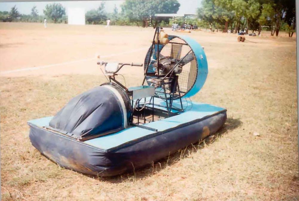
Some of the hull photos are below:-

| More about hull:-
"HULL"
WHICH IS ALSO CALLED AS A SKELETON OF A HOVERCRAFT
UPON WHICH ALL OTHER PARTS ARE BUILT& IT IS MAINLY
RESPONSIBLE FOR PRODUCING AIR CUSHION, SO THAT IT CAN SUPPORT
WHOLE CRAFT. THE HULL IS MADE-UP OF FIBERGLASS, WHICH IS
A VERY LIGHT MATERIAL & HAVING ENOUGH STRENGTH TO WITH
STAND INDUCED STRESSES. THE HULL IS MADE WITH A PROPER DESIGN
SUCH THAT THERE IS A CONTINUOUS SUPPLY OF AIR UNDER
PRESSURE TO REPLACE THE AIR ESCAPING FROM THE UNDERSIDE
OF THE SKIRT.
Usually hull is made up of composite
materials, but in certain cases composite materials by
themselves will not be able to withstand high stresses, so for
this, care must be taken to go for a combination of
conventional as well as composite material. A sandwich
structure of a hull is made up of wood, glass fiber reinforced
plastic and polystyrene is having enough strength to withstand
any kind of load. The wood absorbs most of the stresses
developed while the GRP face sheets absorb normal Stresses. |
OUR EXPERIENCE IN FABRICATION OF HULL IN
DETAIL:
The fabrication of the hull is most
important as the whole structural rigidity is held by it and all the
dynamic machines like the engine, propeller, gear box etc, are
mounted on it.
Initially we had decided to go with a fiber glassed hull material
with mild steel pipe frame. But the idea was dropped due to weight
considerations. Then it was decided that a wooden frame would be
utilized.
The material for fiberglass was obtained from 'Devaki Re-enforcement
limited', sheets measuring 8in by 4in and 6.5in by 2.5in were
obtained. Also glass mat, epoxy resin, catalyst and accelerator were
bought. The 8in by 4in sheet was cut into 1in by 8in
strips. A tray type hull was developed. It was joined using the
glass mat and epoxy resin (refer method of producing fiber glass). A
wooden frame was mounted and stuck to the tray developed using putty
mix, glass mat and epoxy resin.
The base part of the hull was
strengthened by sandwichting a layer of 'pu foam' and a ladder frame
made of wood and aluminium channels, due to the high cost of the
fiber glass sheet, a hard board was used by water proofing it by a
layer of glass mat with epoxy resin that was applied. This made it
waterproof and fit for use. Further two ribs were developed to make
the hull non-flexible and rigid.
The ribs consist of a wooden frame to which a glass fiber plate was
screwed up to make the frame stiff. These ribs were also screwed up
to the hull and then glass mat and epoxy were used to strengthen the
joints as the ribs were to take the load of the engine frames to be
mounted.
|
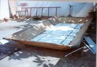 |
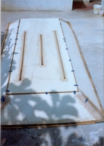
Fig shows when we joined the fiber glass sheets by using
epoxy resin, glass mat, a tray type hull was developed.
The hull is strengthened by sandwichting a layer of 'pu
foam' & a ladder frame made up of aluminium channels & wood. |
|
.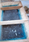 |
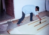
Two ribs were developed to make
the hull non-flexible and rigid. These ribs were also screwed
up to the hull and then glass mat and epoxy were used to
strengthen the joints as the ribs were to take the load of the
engine frames to be mounted. |
Next a bore of diameter 21in was carved out in the hull to provide
space for the air duct or fan casing. The fan casing was stuck to
the hull using glass mat and epoxy.
A wooden piece was provided at the upper portion of curved bore,
which will split the air into the skirt (about 10%) and remaining
portion of air is directed below the hull surface axially.
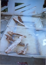
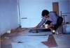 coating epoxy over hard board to make it waterproof.
|