 Early
in 2001 PropReplicator
of the old Prop Message Board arranged a Hardware
Prop Contest. This contest was, in part, a reaction to a growing
number of threads on the board which emphasized the rarity and great
cost of certain 'hero' props some members had acquired, assembled or
created. The contest's aim was two fold; to show each other what
we could do on a relatively level playing field, and to show new members
of the board that you don't have to spend thousands of dollars to get
into the hobby. Whilst I totally lust after those expensive hero
props the contest was very much in line with my own attitude towards
the hobby.
Early
in 2001 PropReplicator
of the old Prop Message Board arranged a Hardware
Prop Contest. This contest was, in part, a reaction to a growing
number of threads on the board which emphasized the rarity and great
cost of certain 'hero' props some members had acquired, assembled or
created. The contest's aim was two fold; to show each other what
we could do on a relatively level playing field, and to show new members
of the board that you don't have to spend thousands of dollars to get
into the hobby. Whilst I totally lust after those expensive hero
props the contest was very much in line with my own attitude towards
the hobby.
Although time was short, only four weeks, I decided I should make time
to support the contest. The basic rules were simple;
- The prop could be from any movie, TV show, comic book or cartoon.
- It had to be made from found items.
- Only hand tools could be used.
- The cost of parts had to be under $20.
With these rules in mind I looked around for a suitable project.
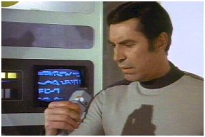
Growing up in the 70's in the UK the show "Space: 1999" was
part of my childhood. I remembered a device that the inhabitants
of Moonbase Alpha used to carry called a Commlock. In the show
the Commlock was a portable communication and locking device with a
multi-function sensor/computer/transceiver. To read more see the
Technical section of the Space
1999 site. What attracted me to this prop was it's simple
shape with no complex curves, and its small size. With the time
and cost constraints this prop fitted the bill perfectly.
Ultimately, the timeframe was too short for me to be able to meet the
deadline but I offer the results of my efforts here nonetheless. I have
yet to finish this project.
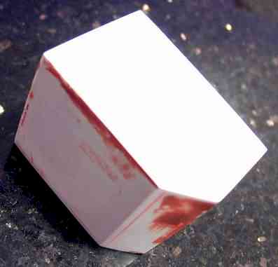
 Cut
out the Video Section from the "No Parking" sign. Print
out the template graphic that
I constructed. Make sure that when you print out you have the
"Print to Page" check-box unchecked to ensure that the image
is printed actual size (1:1). Carefully cut out the Video Section
from your print out and transfer in to the styrene. Cutting the
styrene, even though it seems to be pretty thick, is simple. Using
a steel ruler and a craft knife score the pattern onto the sheet.
If you now bend the styrene along a scored line the styrene will break
pretty cleanly and accurately along the scored line. Put pieces
aside.
Cut
out the Video Section from the "No Parking" sign. Print
out the template graphic that
I constructed. Make sure that when you print out you have the
"Print to Page" check-box unchecked to ensure that the image
is printed actual size (1:1). Carefully cut out the Video Section
from your print out and transfer in to the styrene. Cutting the
styrene, even though it seems to be pretty thick, is simple. Using
a steel ruler and a craft knife score the pattern onto the sheet.
If you now bend the styrene along a scored line the styrene will break
pretty cleanly and accurately along the scored line. Put pieces
aside.
Cut out the Programming/Computer section in the same way and put aside.
Cut out Power Pack/Transmitter section and, again, put aside.
 Assemble
the Video Section. Use a fine, flat file to finish the edges of
the cut pieces. Use a knife to scrape any of the "No Parking"
letters from within 2mm of the edge of each piece all around.
There is no need to remove all the lettering from the sign as it will
be on the inside of the prop and not visible. You do, however,
need to remove any lettering where two edges will come into contact
to be glued as the lettering inhibits the binding action of the glue.
Using super glue carefully assemble the video section. Put aside
for at least an hour to allow the glue to cure.
Assemble
the Video Section. Use a fine, flat file to finish the edges of
the cut pieces. Use a knife to scrape any of the "No Parking"
letters from within 2mm of the edge of each piece all around.
There is no need to remove all the lettering from the sign as it will
be on the inside of the prop and not visible. You do, however,
need to remove any lettering where two edges will come into contact
to be glued as the lettering inhibits the binding action of the glue.
Using super glue carefully assemble the video section. Put aside
for at least an hour to allow the glue to cure.
 Assemble
the Programming/Computer section in the same way.
Assemble
the Programming/Computer section in the same way.
Ditto for the Power Pack/Transmitter section.
Finish each of the three sections by first sanding down and protruding
edges. Next fill any recesses or cracks along your joins that
require it with putty or Bondo. Finally, once your filler has
cured, sand each piece with progressively fine grit paper attached to
a sanding block or wood scrap.
Drill and cut out the hole for the TV screen in the top part of the
Video Section using your template. This hole will not be seen
when the prop is finished.
Cut the hole that the belt clip will fit through. Use an appropriately
small drill bit then complete and finish the slit with a small rat's
tail file.
Drill the hole in the Power Pack/Transmitter section to accept the
antenna tube. File the hole smooth and test fit the tube to check
that the fit is snug.
 Cut
a 14cm length from the riser tube. This tube will not only provide
the visible antenna for the commlock but will also provide the back
bone of this prop, giving it strength as we shall see in a moment.
File and sand the cut end of the tube flat as this will be the seen
end. The other end may have threads on it but don't worry about
them as they will be inside the prop and will not be seen.
Cut
a 14cm length from the riser tube. This tube will not only provide
the visible antenna for the commlock but will also provide the back
bone of this prop, giving it strength as we shall see in a moment.
File and sand the cut end of the tube flat as this will be the seen
end. The other end may have threads on it but don't worry about
them as they will be inside the prop and will not be seen.
Cut out the clip from the sheet aluminum using the template
as your guide. You can use a hacksaw although a Dremel tool
and small cutting wheel will be much faster.
Finish the clip using a flat file and emery cloth. Once the edges
are smooth and even use a vice to bend the aluminum into the clip shape.
Set aside.
Cut out and finish the edges of the two subsections but do not assemble
them yet. Set the pieces aside.
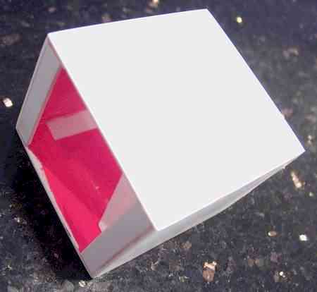
Cut out the screen shade.
 Assemble
the screen shade.
Assemble
the screen shade.
 Fit
the antenna into the Transmitter section and epoxy into place.
Fit
the antenna into the Transmitter section and epoxy into place.
Once the epoxy has cured use water putty cast into the bottom half
of the Transmitter section. This will provide strength and also
realistic weight when the prop is finish.
Paint the area of the black line and the other parallel detail lines
on the antenna and Transmitter section. At the same time you should
paint the surfaces of the subsections that will show when the prop is
assembled and the belt-clip.
When the black paint has fully dried mask off the line using the thin
pin lining masking tape that you find at model and art stores.
Also mask the parallel line details. You want the masking tape
to be 2mm wide.
Spray paint the three main sections.
Attach the Computer and Transmitter Sections using the bottom sub-section.
Attach the Video and Computer Sections using the top sub-section.
Fit the clip into place in the video section and epoxy into place.
Cast the interior with water putty up to the top of the tube but leaving
the tube clear. Again this provides strength and heft. It
will also hold the belt clip permanently in place.
Image and clear screen.
Screen shade.
Plug
Id Card
Computer interface
Speaker
Silver detail
Key pad
Round buttons
Square buttons.

