 |
search engine here |
||
|
|||
| STANDARDS |
|
BROADCAST STANDARDS |
||||||||||||||||||||||||||||||||||||||||||||||||||||||||||||
Video actually is a sequence of pictures, each picture is consisted by an array of pixel. For a uncompression video, its size is huge. Such as CCIRR-601 parametes (720pixels x 480pixels x 30frames/s), it has a data rate at about 165Mbps. This high data rate is too high for user-level application and it is a big problem for CPU and communication. To deal with this problem, video compression is used in order to reduce the size. There are two kinds of compression method, one is lossless and the other is lossy. For a lossless compression, such as Huffman, Arithmetic, LZW..etc, they do not work well for video since the distribution of pixel value is wide range. So in the following parts, we will discuss how to compress a video by using MPEG standard. MPEG is an acronym for Moving Picture Expets Group, a committee formed by the ISO(International Organization for Standardization) to develop this standard. MPEG was formed in 1988 to establish an international standard for the coded representation of moving pictures and association audio on digital storage media. Currently there are three MPEG stardards.
The MPEG-2 Standard is published in four parts. Part 1: Systems specifies the system coding layer of the MPEG-2. It defines a multiplexed structure for combining audio and video data and means of representation the timing information needed to replay synchronized sequences in real time. Part 2: Video specifies the coded representation of video data and the decoding precess required to reconstruct pictures. Part 3: Audio specifies the coded representation of audio data. Part 4: Conformance test MPEG-2 was developed by ISO/IEC/JTC/SC29/WG11 and is known as ISO/IEC 13818. The MPEG-2 video coding standard is primarily aimed at coding of CCIRR-601 or higher resolution video with fairly high quality at challenging bitrates of 4 to 9Mbit/s. It aims at providing CCIR/ITU-R quality for NTSC, PAL, and SECAM, and also at supporting HDTV quality, at data rate above 10Mbps, real-time transmission, and progressive and interlaced scan sources.
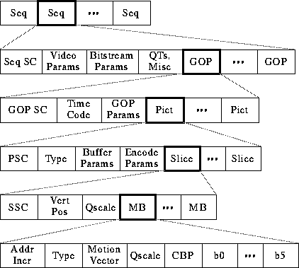
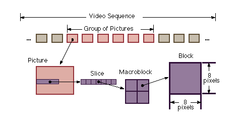
From the above video bitstream, we can see that it is consisted by 4 layer : GOP, Pictures, Slice, Macroblock, Block.
Video Sequence Begins with a squence header (may contain additiomal sequence header), includes one or more groups of pictures, and ends with an end-of-sequence code. Group of Pictures (GOP) A Header and a series of one of more pictures intended to allow random access into the sequence. Picture The primary coding unit of a video sequence. A picture consists of three rectanguar matrices representing luminance (Y) and two chrominance (Cb and Cr) values. The Y matrix has an even number of rows and columns. The Cb and Cr matrices are one-half the size of the Y matrix in each direction (horizontal and vertical). Slice One or more "contiguous" macroblocks. The order of the macroblocks within a slice is from left-to-right and top-to-bottom. Slice are important in the handling of erros. If the bitstream contains an error, the decoder can skip to the start of the next slice. Having more slices in the bitstream allows better error concealment, but uses bits that could otherwise be used to improve picture quality. Macroblock
The basic coding unit in the MPEG algorithm. It is a 16x 16 pixel segment in a frame. Since each chrominance component has one-half the vertical and horizontal resolution of the luminance component, a macroblock consists of four Y, one Cr, and one Cb block. Block The smallest coding unit in the MPEG algorithm. It consists of 8x8 pixels and can be one of three types: luminance(Y), red chrominance(Cr), or blue chrominance(Cb). The block is the basic unit in intra frame coding.
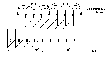
The MPEG standard specifically defines three types of pictures: These three types of pictures are combined to form a group of picture.
Intra Pictures Intra pictures, or I-Picture, are coded using only information present in the picture itself, and provides potential random access points into the compressed video data. It uses only transform coding and provide moderate compression. Typically it uses about two bits per coded pixel. Predicted Pictures Predicted pictures, or P-pictures, are coded with respect
to the nearest previous I- or P-pictures. This technique is called forward
prediction and is illustrated in above figure. Bidirectional Pictures Bidirectional pictures, or B-pictures, are pictures that use both a past and future picture as a reference. This technique is called bidirectional prediction. B-pictures provide the most compression since it use the past and future picture as a regerence, however, the computation time is the largerest.
Intra Pictures
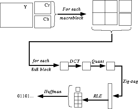
The MPEG transform coding algorithm includes the following steps: Both image blocks and prediction-error blocks have high spatial redundancy. To reduce this redundancy, the MPEG algorithm transforms 8x8 blocks of pixels or 8x8 blocks of error terms from the spatial domain to the frequency domain with the discrete Cosine Transform (DCT). The combination of DCT and quantization results in many of the frequency coefficients being zero, especially the coefficients for high spatial frequencies. To take maximum advantage of this, the coefficients are organized in a zigzag order to produce long runs of zero. The coefficients are then converted to a series of run-amplitude pairs, each pair indicating a number of zero coefficeints and the amplitude of a non-zero coefficient. These run-amplitude pairs are then coded with a variable-length code(Huffman Encoding), which uses shorter codes for commonly occurring pairs and longer codes for less common pairs. Some blocks of pixels need to be coded more accurately than others. for example, blocks with smooth intensity gradients need accurate coding to avoid visbile block boundaries. To deal with this inequality between blocks, the MPEG algorithm allows the amount of quantization to be modified for each macroblock of pixels. This mechanism can also be used to provide smooth adaptation to particular bit rate. Predicted Pictures
Motion compensation based prediction exploits the temporal redundancy. Due to frames are closely related, it is possible to accurately represent or "predict" the data of one frame based on the data of a reference image, provided the translation is estimated. The process of prediction helps in the reduction of bits by a huge amont. In P-Pictures, each 16x16 sized macroblock is predicted from a macroblock of a previously encoded I picture. Sinces, frames are snapshots in time of a moving object, the macroblocks in the two frames may not be cosited, i.e. correspond to the same spatial location. Hence, a search is conducted in the I frame to find the macroblock which closely matches the macroblock under consideration in the P frame. The difference between the two macroblock is the prediction error. This error can be coded in the DCTdomain. The DCTof the errr results in few high frequency coefficients, which after the quantization process require a small number of bits for represenation. The quantization matrices for the prediction error blocks are different from those used in intra block, due to the distinct nature of their frequency spectrum. The displacements in the horizaontal and vertical directions of the best match macroblock from the cosited macroblock are called motion vectors. Differential coding is used because it reduces the total bit requirement by transmitting the difference between the motion vectors of consecutinve frames. Finally it use the run-length encoding and huffman encoding to encode the data. Biderectional Pictures example:
From the above pictures, there are some information which is not in the reference frame. Hence B picture is coded like P-pictures except the motion vectors can reference either the previous reference picture, the next picture, or both. The following is the machanism of B-picture coding.
MPEG-2 is designed to support a wide range of applications and services of varying bit rate, resolution, and quality. MPEG-2 standards defines 4 profiles and 4 levels for ensuring inter-operability of these applications. The profile defines the colorspace resolution, and scalability of the bitscream. The levels define the maximum and minumum for image resolution, and Y (Luminance) samples per second, the number of video and audio layers supported for scalable profiles, and the maximum bit rate per profile. The video decoder will depend on it's availibility and need to handle the particular bitstream.
Scalable video is only available on Main+ and Next profile. Currently there are four scalable modes in the MPEG-2 toolkit. These modes break MPEG-2 video into different layers. Spatial Scalability Useful in simulcasting, and for feasible software decoding of the lower resolution, base layer. This spatial domain method codes a base layer at lower sampling dimensions (i.e. resolution) than the upper layers. The upsampled reconstructed lower (base) layers are then used as prediction for the higher layers. Data Partitioning Similar to JPEG's frequency progressive mode, only the slice layer indicates the maximum number of block transform coefficients contained in the particular bitstream (known as the priority break point). Data partitioning is a frequency domain method that breaks the block of 64 quantized transform coefficients into two bitstreams. The first, higher priority bitstream contains the more critical lower frequency coefficients and side informations (such as DC values, motion vectors). The second, lower priority bitstream carries higher frequency AC data. SNR Scalability Similar to the point transform in JPEG, SNR scalability is a spatial domain method where channels are coded at identical sample rates, but with differing picture quality (through quantization step sizes). The higher priority bitstream contains base layer data that can be added to a lower priority refinement layer to construct a higher quality picture. Temporal Scalability A temporal domain method useful in, e.g., stereoscopic video. The first, higher priority bitstreams codes video at a lower frame rate, and the intermediate frames can be coded in a second bitstream using the first bitstream reconstruction as prediction. In stereoscopic vision, for example, the left video channel can be predicted from the right channel.
Interlaced Video and Picture Structures MPEG-2 support two scanning methods, one is progressive scanning and the other is interlaced scanning. Interlaced scanning scans odd lines of a frame as one field (odd field), and even lines as another field (even field). Progressive scanning scans the consecutive lines in sequential order. An interlaced video sequence uses on of two picture structures: frame structure and field structure. In the frame structure, lines of two fields alternate and the two fields are coded together as a frame. One picture header is used for two fields. In the field structure, the two fields of a frame may be coded independently of each other, and the odd field is followed by the even field. Each of the two fields has its picture header. The interlaced video sequence can switch between frame structres and field structures on a picture-by-pictures basics. On the other hand, each picture in a progressive video sequence is a frame picture.
MPEG-2 provides a low bitrate coding for multichannel audio.Totally there are five full bandwidth channels (left, right, center, and two surround channels), plus a additional low frequency enhancement channel, and/or up to seven commentary/multilingual multilangual channel. The MPEG-2 Audio Standard will also extend the stereo and mono coding of MPEG-1 Audio Standard (ISO/IEC IS 11172-3) to half sampling rates (16 kHz, 22.05 kHz and 24 kHz), for improved quality for bitrate at or below 64 kbits/s, per channel |
||||||||||||||||||||||||||||||||||||||||||||||||||||||||||||
courtesy of Victor Lo |
A Personal initiative of the author Engr.Jolan P. Formalejo.


